|

 Up
Up
 Making The
Flyer Fly

(You are here.)

  Need
to Need
to
find your
bearings?
Try
these
navigation aids:
If
this is your first
visit, please stop by:
Something
to share?
Please:
|
|
Available in Française, Español, Português, Deutsch, Россию,
中文,
日本, and others.
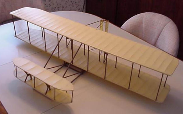
By Pat Tritle
Pat's Custom Models/Dare Design
 everal years
ago the idea to design and build a truly flyable 1903 Wright Type A Flyer
was discussed as a possible kit offering suitable for the average R/C
(Remote Control) modeler. Up until that time the Wright Type "A"
Flyer was considered un-flyable as an R/C model, but it seemed like a fair
challenge, so we decided to go ahead with the project. everal years
ago the idea to design and build a truly flyable 1903 Wright Type A Flyer
was discussed as a possible kit offering suitable for the average R/C
(Remote Control) modeler. Up until that time the Wright Type "A"
Flyer was considered un-flyable as an R/C model, but it seemed like a fair
challenge, so we decided to go ahead with the project. The design began using the Paul Matt 3-view drawings. In studying the
drawings and planning the model design I decided that to be suitable for
the average builder the model would have to be kept as simple as possible.
As a result, I decided to control the model using the canard, rudder and
throttle rather than wing warping which in itself would have complicated
the design beyond my original goal. I have always felt that flying quality
should take priority over accuracy in outline.
The power system would also need to be simple and reliable. For that
reason I chose to use two geared electric motors operating through a
single electronic speed control. Unfortunately, reverse pitch props are
not available, so counter rotation wouldn’t be possible unless the
builder opted to carve his own props. Micro servos were used to operate
the rudder and canard. I also knew that to turn the model without warping
the wing, the wing would need a small amount of dihedral. Lastly, I opted
to build the wing centerline on center rather than with the asymmetrical
centerline. Within those parameters, the overall scale outline and
airfoils would be retained for initial flight testing.
Flight Testing
The first test flights proved to be a dismal failure. The model was
hand launched at full power and flew right into the ground! Repairs were
made, including the addition of a more positive canard neutral point and
the second attempt was made. The result was the same as the fist. After
several small changes to the basic set-up, including altering the balance
point and lengthening the fuselage, it was obvious the model was not going
to fly, and at this point the prototype was battered beyond further
repair.
Fortunately, the first three attempts to fly were video taped. With a
careful review of the video I determined that it wasn’t dropping the
nose, but the wing was actually over-flying the canard causing the
downward angle of attack, so a new prototype was build using a flat bottom
airfoil rather than the scale under-camber. The airfoil on the canard was
changed to a deeper under-camber in an attempt to equalize the lifting
ability of both the wing and canard. At this point I still had a bad
feeling about the overall design, so I put the R/C model aside and built a
1/3 scale glider model of the R/C model.
Testing the Concept Using a Glider
Initial test flights on the solid balsa glider model proved to be very
inconsistent. After several changes in the canard angle and CG (Center of
Gravity) the model still proved itself too inconsistent and unstable to be
practical.
The next step was to increase the canard span and chord 25% and
relocating the CG back to its’ original location. That turned out to be
the solution to all of the Flyers’ ills. From that point on, the Flyer
was as stable and honest as any other glider I’ve flown in its’ size
range. So, the changes were incorporated into the R/C model and flight
testing resumed.
Success at Last!
The first test flight on the new prototype proved to be as successful
as anyone could hope for! The model was very sensitive to pitch control
but trimmed easily for level flight and turned well on the rudder. The
power system proved adequate, and when trimmed properly would fly nicely
at 2/3 power. Do to the nature of the "Flyer", I didn’t
attempt any maneuvering beyond gentle turns in both directions. As a
result of prop torque, the model turns better to the right then the left,
but is very controllable in either direction. After 20 or so test flights
making minor changes I determined the model to be ready for the average
modeler to build and fly, and to prove the point, a third prototype was
built. The third model actually flew a bit better then the second, only
because more care was taken to insure the model was straight and true.
Looking Back
Looking back over the course of development of the model, it occurred
to me that this was without a doubt, the most challenging and rewarding
design I have ever been involved in. To have the opportunity to work with
this design really brings to mind what the Wright Brothers had to overcome
to accomplish that first powered flight almost 100 years ago.
|
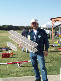
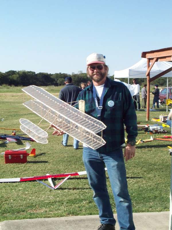
Pat Tritle with his RC Model Wright Flyer.
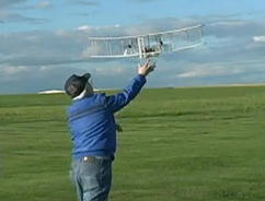
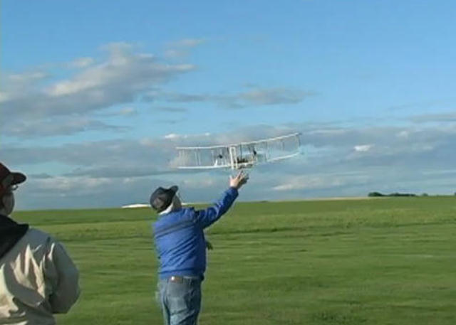
Launching the RC Flyer.
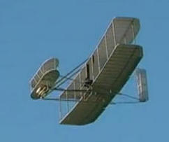
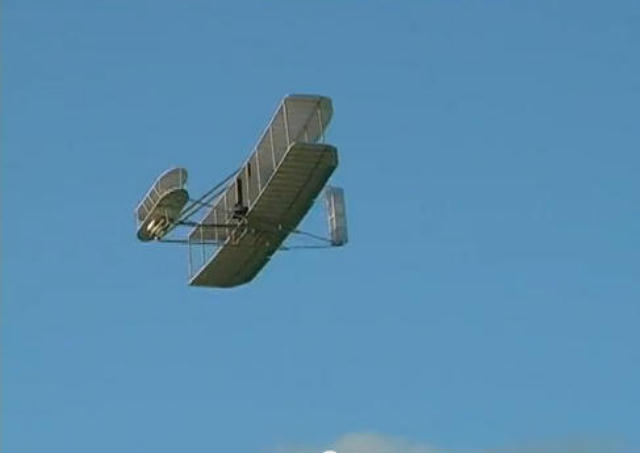
The Flyer in flight.
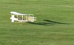
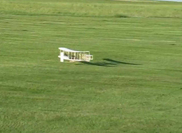
Landing the Flyer.

You can build a very capable Wright Glider from either of the Dare kits
– electric- powered of rubber
band-powered. Simply don't install the drive train or RC controls.
Note: f you would like to see a Dare RC Wright Flyer in
flight, click
HERE.
|