|
In
Their Own Words
 his is the
final form of Wilbur and Orville Wright's patent for "new and useful
improvements in Flying-Machines." his is the
final form of Wilbur and Orville Wright's patent for "new and useful
improvements in Flying-Machines."
UNITED STATES PATENT OFFICE.
ORVILLE WRIGHT AND WILBUR WRIGHT, OF DAYTON, OHIO.
FLYING-MACHINE.
No 821,393. Specification of Letters Patent. Patented May 22, 1906.
Application filed March 23, 1903 Serial No. 149,220
To all whom it may concern: Be it known that we, ORVILLE WRIGHT and
WILBUR WRIGHT, citizens of the United States, residing in the city of
Dayton, county of Montgomery, and State of Ohio, have in vented certain
new and useful Improvements in Flying-Machines, of which the following is
a specification. Our invention relates to that class of flying machines in
which the weight is sustained by the reactions resulting when one or more
aeroplanes are moved through the air edgewise at a small angle of
incidence, either by the application of mechanical power or by the
utilization of the force of gravity. The objects of our invention are to
provide means for maintaining or restoring the equilibrium or lateral
balance of the apparatus, to provide means for guiding the machine both
vertically and horizontally, and to provide a structure combining
lightness, strength, convenience of construction, and certain other
advantages which will hereinafter appear.
To these ends our invention consists in certain novel features, which
we will now proceed to describe and will then particularly point out in
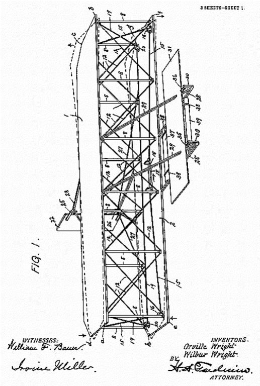
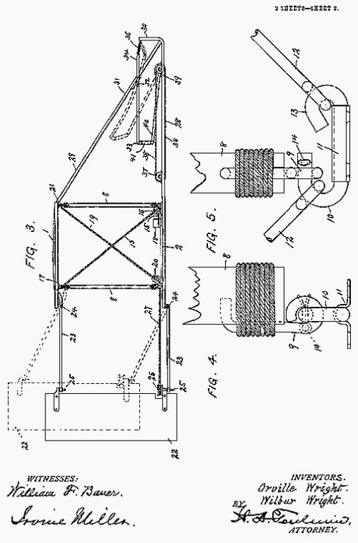
the claims. In the accompanying drawings, Figure 1 is a perspective view
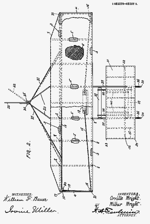
of an apparatus embodying our invention in one form. Fig. 2 is a plan view
of the same, partly in horizontal section and partly broken away. Fig. 3
is a side elevation, and Figs. 4 and 5 are detail views, of one form of
flexible joint for connecting the upright standards with the aeroplanes.
In flying-machines of the character to which this invention relates the
apparatus is supported in the air by reason of the contact between the air
and the under surface of one or more aeroplanes, the contact-surface being
presented at a small angle of incidence to the air. The relative movements
of the air and aeroplane may be derived from the motion of the air in the
form of wind blowing in the direction opposite to that in which the
apparatus is traveling or by a combined downward and forward movement of
the machine, as in starting from an elevated position or by combination of
these two things, and in either case the operation is that of a
soaring-machine, while power applied to the machine to propel it
positively forward will cause the air to support the machine in a similar
manner. In either case owing to the varying conditions to be met there are
numerous disturbing forces which tend to shift the machine from the
position which it should occupy to obtain the desired results. It is the
chief object of our invention to provide means for remedying this
difficulty, and we will now proceed to describe the construction by means
of which these results are accomplished. In the accompanying drawings we
have shown an apparatus embodying our invention in one form. In this
illustrative embodiment the machine is shown as comprising two parallel
superposed aeroplanes 1 and 2, and this construction we prefer, although
our invention may be embodied in a structure having a single aeroplane.
Each aeroplane is of considerably greater width from side to side than
from front to rear. The four corners of the upper aeroplane are indicated
by the reference-letters a, b, c, and d, while the corresponding corners
of the lower aeroplane 2 are indicated by the reference-letters e, f, g,
and h. The marginal lines a b and e f indicate the front edges of the
aeroplanes, the lateral margins of the upper aeroplane are indicated,
respectively, by the lines a d and b c, the lateral margins of the lower
aeroplane are indicated, respectively, by the lines e h and f g, while the
rear margins of the upper and lower aeroplanes are indicated,
respectively, by the lines c d and g h. Before proceeding to a description
of the fundamental theory of operation of the structure we will first
describe the preferred mode of constructing the aeroplanes and those
portions of the structure which serve to connect the two aeroplanes. Each
aeroplane is formed by stretching cloth or other suitable fabric over a
frame composed of two parallel traverse spars 3, extending from side to
side of the machine, their ends being connected by bows 4, extending from
front to rear of the machine. The front and rear spars 3 of each aeroplane
are connected by a series of parallel ribs 5, which preferably extend
somewhat beyond the rear spar, as shown. These spars, bows, and ribs are
preferably constructed of wood having the necessary strength, combined
with lightness and flexibility. Upon this framework the cloth which forms
the supporting-surface of the aeroplane is secured, the frame being
enclosed in the cloth. The cloth for each aeroplane previously to its
attachment to its frame is cut on the bias and made up into a single piece
approximately the size and shape of the aeroplane, having the threads of
the fabric arranged diagonally to the transverse spars and longitudinal
ribs, as indicated at 6 in Fig. 2. Thus the diagonal threads of the cloth
form truss systems with the spars and ribs, the threads constituting the
diagonal members. A hem is formed at the rear edge of the cloth to receive
a wire 7, which is connected to the ends of the rear spar and supported by
the rearwardly-extending ends of the longitudinal ribs 5, thus forming a
rearwardly-extending flap or portion of the aeroplane. This construction
of the aeroplanes gives a surface which has very great strength to
withstand lateral and longitudinal strains, at the same time being capable
of being bent or twisted in the manner hereinafter described. When two
aeroplanes are employed, as in the construction illustrated, they are
connected together by upright standards 8. These standards are
substantially rigid, being preferably constructed of wood and of equal
length, equally spaced along the front and rear edges of the aeroplane, to
which they are connected at their top and bottom ends by hinged joints or
universal joints of any suitable description. We have shown one form of
connection which may be used for this purpose in Figs. 4 and 5 of the
drawings. In this construction each end of the standard 8 has secured to
it an eye 9, which engages with a hook 10, secured to a bracket plate 11,
which latter plate is in turn fastened to the spar 3. Diagonal braces or
stay wires 12 extend from each end of each standard to the opposite ends
of the adjacent standards, and as a convenient mode of attaching these
parts I have shown a hook 13 made integral with the hook 10 to receive the
end of one of the stay-wires, the other stay-wire being mounted on the
hook 10. The hook 13 is shown as bent down to retain hook 10 is shown as
provided with a pin 14 to hold the stay-wire 12 and eye 9 in position
thereon. It will be seen that this construction forms a truss system which
gives the whole machine great transverse rigidity and strength, while at
the same time the jointed connections of the parts permit the aeroplanes
to be bent or twisted in the manner which we will now proceed to describe.
15 indicates a rope or other flexible connection extending lengthwise of
the front of the machine above the lower aeroplane, passing under pulleys
or other suitable guides 16 at the front corners e and f of the lower
aeroplane, and extending thence upward and rearward to the upper rear
corners c and d
of the upper aeroplane, where they are attached, as indicated at 17. To
the central portion of this rope there is connected a laterally-movable
cradle 18, which forms a means for moving the rope lengthwise in one
direction or the other, the cradle being movable toward either side of the
machine. We have devised this cradle as a convenient means for operating
the rope 15, and the machine is intended to be generally used with the
operator lying face downward on the lower aeroplane, with his head to the
front, so that the operator's body rests on the cradle, and the cradle can
be moved laterally by the movements of the operator's body. It will be
understood, however, that the rope 15 may be manipulated in any suitable
manner. 19 indicates a second rope extending transversely of the machine
along the rear edge of the body portion of the lower aeroplane, passing
under suitable pulleys or guides 20 at the rear corners g and h of the
lower aeroplane, and extending thence diagonally upward to the front
corners a and b of the upper aeroplane, where its ends are secured in any
suitable manner, as indicated at 21.
Considering the structure so far as we have now described it and
assuming that the cradle 18 be moved to the right in Figs. 1 and 2, as
indicated by the arrows applied to the cradle in Fig. 1 and by the dotted
lines in Fig. 2, it will be seen that that portion of the rope 15 passing
under the guide-pulley at the corner e and secured to the corner d will be
under tension, while slack is paid out throughout the other side or half
of the rope 15. The part of the rope 15 under tension exercises a downward
pull upon the rear upper corner d of the structure and an upward pull upon
the front lower corner e, as indicated by the arrows. This causes the
corner d to move downward and the corner e to move upward. As the corner e
moves upward it carries the corner a upward with it, since the
intermediate standard 8 is substantially rigid and maintains an equal
distance between the corners a and e at all times. Similarly, the standard
8, connecting the corners d and h, causes the corner h to move downward in
unison with the corner d. Since the corner a thus moves upward and the
corner h moves downward, that portion of the rope 19 connected to the
corner a will be pulled upward through the pulley 20 at the corner h, and
the pull thus exerted on the rope 19 will pull the corner b on the other
side of the machine downward and at the same time pull the corner g at
said other side of the machine upward. This results in a downward movement
of the corner b and an upward movement of the corner c. Thus it results
from a lateral movement of the cradle 18 to the right in Fig. 1 that the
lateral margins a d and e h at one side of the machine are moved from
their normal positions, in which they lie in the normal planes of their
respective aeroplanes, into angular relations with said normal planes,
each lateral margin on this side of the machine being raised above said
normal plane at its forward end and depressed below said normal plane at
its rear end, said lateral margins being thus inclined upward and forward.
At the same time a reverse inclination is imparted to the lateral margins
b c and f g at the other side of the machine, their inclination being
downward and forward. These positions are indicated in dotted lines in
Fig. 1 of the drawings. A movement of the cradle 18 in the opposite
direction from its normal position will reverse the angular inclination of
obvious manner. By reason of this construction it will be seen that with
the particular mode of construction now under consideration it is possible
to move the forward corner of the lateral edges of the aeroplane on one
side of the machine either above or below the normal planes of the
aeroplanes, a reverse movement of the forward corners of the lateral
margins on the other side of the machine occurring simultaneously. During
this operation each aeroplane is twisted or distorted around a line
extending centrally across the same from the middle of one lateral margin
to the middle of the other lateral margin, the twist due to the moving of
the lateral margins to different angles extending across each aeroplane
from side to side, so that each aeroplane surface is given a helicoidal
warp or twist. We prefer this construction and mode of operation for the
reason that it gives a gradually-increasing angle to the body of each
aeroplane from the central longitudinal line thereof outward to the
margin, thus giving a continuous surface on each side of the machine,
which has a gradually increasing or decreasing angle of incidence from the
center of the machine to either side. We wish it to be understood,
however, that our invention is not limited to this particular
construction, since any construction whereby the angular relations of the
lateral margins of the aeroplanes may be varied in opposite directions
with respect to the normal planes of said aeroplanes comes within the
scope of our invention. Furthermore, it should be understood that while
the lateral margins of the aeroplanes move to different angular positions
with respect to or above and below the normal planes of said aeroplanes it
does not necessarily follow that these movements bring the opposite
lateral edges to different angles respectively above and below a
horizontal plane, since the normal planes of the bodies of the aeroplanes
are inclined to the horizontal when the machine is in flight, said
inclination being downward from front to rear, and while the forward
corners on one side of the machine may be depressed below the normal
planes of the bodies of the aeroplanes said depression is not necessarily
sufficient to carry them below the horizontal planes passing through the
rear corners on that side. Moreover, although we prefer to so construct
the apparatus that the movements of the lateral margins on the opposite
sides of the machine are equal in extent and opposite in direction, yet
our invention is not limited to a construction producing this result,
since it may be desirable under certain circumstances to move the lateral
margins on one side of the machine in the manner just described without
moving the lateral margins on the other side of the machine to an equal
extent in the opposite direction. Turning now to the purpose of this
provision for moving the lateral margins of the aeroplanes in the manner
described, it should be premised that owing to various conditions of
wind-pressure and other causes the body of the machine is apt to become
unbalanced laterally, one side tending to sink and the other side tending
to rise, the machine turning around its central longitudinal axis. The
provision which we have just described enables the operator to meet this
difficulty and preserve the lateral balance of the machine. Assuming that
for some cause the side of the machine which lies to the left of the
observer in Figs. 1 and 2 has shown a tendency to drop downward, a
movement of the cradle 18 to the right of said figures, as hereinbefore
assumed, will move the lateral margins of the aeroplanes in the manner
already described, so that the margins a d and e h will be inclined
downward and rearward and the lateral margins b c and f g will be inclined
upward and rearward with respect to the normal planes of the bodies of the
aeroplanes. With the parts of the machine in this position it will be seen
that the lateral margins a d and e h present a larger angle of incidence
to the resisting air, while the lateral margins on the other side of the
machine present a smaller angle of incidence. Owing to this fact, the side
of the machine presenting the larger angle of incidence will tend to lift
or move upward, and this upward movement will restore the lateral balance
of the machine. When the other side of the machine tends to drop, a
movement of the cradle 18 in the reverse direction will restore the
machine to its normal lateral equilibrium. Of course the same effect will
be produced in the same way in the case of a machine employing only a
single aeroplane.
In connection with the body of the machine as thus operated we employ a
vertical rudder or tail 22, so supported as to turn around a vertical
axis. This rudder is supported at the rear ends of supports or arms 23,
pivoted at their forward ends to the rear margins of the upper and lower
aeroplanes, respectively. These supports are preferably V-shaped, as
shown, so that their forward ends are comparatively widely separated,
their pivots being indicated at 24. Said supports are free to swing upward
at their free rear ends, as indicated in dotted lines in Fig. 3, their
downward movement being limited in any suitable manner. The vertical
pivots of the rudder 22 are indicated at 25, and one of these pivots has
mounted thereon a sheave or pulley 26, around which passes a tiller-rope
27, the ends of which are extended out laterally and secured to the rope
19 on opposite sides of the central point of said rope. By reason of this
construction the lateral shifting of the cradle 18 serves to turn the
rudder to one side or the other of the line of flight. It will be observed
in this connection that the construction is such that the rudder will
always be so turned as to present its resisting-surface on that side of
the machine on which the lateral margins of the aeroplanes present the
least angle of resistance. The reason of this construction is that when
the lateral margins of the aeroplanes are so turned in the manner
hereinbefore described as to present different angles of incidence to
the atmosphere that side presenting the largest angle of incidence,
although being lifted or moved upward in the manner already described, at
the same time meets with an increased resistance to its forward motion,
and is therefore retarded in its forward motion, while at the same time
the other side of the machine, presenting a smaller angle of incidence,
meets with less resistance to its forward motion and tends to move forward
more rapidly than the retarded side. This gives the machine a tendency to
turn around its vertical axis, and this tendency if not properly met will
not only change the direction of the front of the machine, but will
ultimately permit one side thereof to drop into a position vertically
below the other side with the aeroplanes in vertical position, thus
causing the machine to fall. The movement of the rudder hereinbefore
described prevents this action, since it exerts a retarding influence on
that side of the machine which tends to move forward too rapidly and keeps
the machine with its front properly presented to the direction of flight
and with its body properly balanced around its central longitudinal axis.
The pivoting of the supports 23 so as to permit them to swing upward
prevents injury to the rudder and its supports in case the machine alights
at such an angle as to cause the rudder to strike the ground first, the
parts yielding upward, as indicated in dotted lines in Fig. 3, and thus
preventing injury or breakage. We wish it to be understood, however, that
we do not limit ourselves to the particular description of rudder set
forth, the essential being that the rudder shall be vertical and shall be
so moved as to present its resisting-surface on that side of the machine
which offers the least resistance to the atmosphere, so as to counteract
the tendency of the machine to turn around a vertical axis when the two
sides thereof offer different resistances to the air.
From the central portion of the front of the machine struts 28 extend
horizontally for ward from the lower aeroplane, and struts 29 extend
downward and forward from the central portion of the upper aeroplane,
their front ends being united to the struts 28, the forward extremities of
which are turned up, as indicated at 30. These struts 28 and 29 form
truss-skids projecting in front of the whole frame of the machine and
serving to prevent the machine from rolling over forward when it alights.
The struts 29 serve to brace the upper portion of the main frame and
resist its tendency to move forward after the lower aeroplane has been
stopped by its contact with the earth, thereby relieving the rope 19 from
undue strain, for it will be understood that when the machine comes into
contact with the earth further forward movement of the lower portion
thereof being suddenly arrested the inertia of the upper portion would
tend to cause it to continue to move forward if not prevented by the
struts 29, and this forward movement of the upper portion would bring a
very violent strain upon the rope 19, since it is fastened to the upper
portion at both of its ends, while its lower portion is connected by the
guides 20 to the lower portion. The struts 28 and 29 also serve to support
the front or horizontal rudder, the construction of which we will now
proceed to describe. The front rudder 31 is a horizontal rudder having a
flexible body, the same consisting of three stiff cross-pieces or sticks
32, 33, and 34, and the flexible ribs 35, connecting said crosspieces and
extending from front to rear. The frame thus provided is covered by a
suitable fabric stretched over the same to form the body of the rudder.
The rudder is supported from the struts 29 by means of the intermediate
cross-piece 32, which is located near the center of pressure slightly in
front of a line equidistant between the front and rear edges of the
rudder, the cross-piece 32 forming the pivotal axis of the rudder, so as
to constitute a balanced rudder. To the front edge of the rudder there are
connected springs 36, which springs are connected to the upturned ends 30
of the struts 28, the construction being such that said springs tend to
resist any movement either upward or downward of the front edge of the
horizontal rudder. The rear edge of the rudder lies immediately in front of
the operator and may be operated by him in any suitable manner. We
have shown a mechanism for this purpose comprising a roller or shaft 37,
which may be grasped by the operator so as to turn the same in either
direction. Bands 38 extend from the roller 37 forward to and around a
similar roller or shaft 39, both rollers or shafts being supported in
suitable bearings on the struts 28. The forward roller or shaft has
rearwardly-extending arms 40, which are connected by links 41 with the rear
edge of the rudder 31. The normal position of the rudder 31 is neutral or
substantially parallel with the aeroplanes 1 and 2; but its rear edge may
be moved upward or downward, so as to be above or below the normal plane
of said rudder through the mechanism provided for that purpose. It will be
seen that the springs 36 will resist any tendency of the forward edge of
the rudder to move in either direction, so that when force is applied to
the rear edge of said rudder the longitudinal ribs 35 bend, and the rudder
thus presents a concave surface to the action of the wind either above or
below its normal plane, said surface presenting a small angle of incidence
at its forward portion and said angle of incidence rapidly increasing
toward the rear. This greatly increases the efficiency of the rudder as
compared with a plane surface of equal area. By regulating the pressure on
the upper and lower sides of the rudder through changes of angle and
curvature in the manner described a turning movement of the main structure
around its transverse axis may be effected, and the course of the machine
may thus be directed upward or downward at the will of the operator and
the longitudinal balance thereof maintained. Contrary to the usual custom,
we place the horizontal rudder in front of the aeroplanes at a negative
angle and employ no horizontal tail at all. By this arrangement we obtain
a forward surface which is almost entirely free from pressure under
ordinary conditions of flight, but which even if not moved at all from its
original position becomes an efficient lifting-surface whenever the speed
of the machine is accidentally reduced very much below the normal, and
thus largely counteracts that backward travel of the center of pressure on
the aeroplanes which has frequently been productive of serious injuries by
causing the machine to turn downward and forward and strike the ground
head-on. We are aware that a forward horizontal rudder of different
construction has been used in combination with a supporting-surface and a
rear horizontal rudder; but this combination was not intended to effect
and does not effect the object which we obtain by the arrangement
hereinbefore described.
We have used the term "aeroplane" in this specification and
the appended claims to indicate the supporting-surface or supporting
surfaces by means of which the machine is sustained in the air, and by
this term we wish to be understood as including any suitable
supporting-surface which normally is substantially flat, although of
course when constructed of cloth or other flexible fabric, as we prefer to
construct them, these surfaces may receive more or less curvature from the
resistance of the air, as indicated in Fig. 3. We do not wish to be
understood as limiting ourselves strictly to the precise details of
construction hereinbefore described and shown in the accompanying
drawings, as it is obvious that these details may be modified without
departing from the principles of our invention. For instance, while we
prefer the construction illustrated in which each aeroplane is given a
twist along its entire length in order to set its opposite lateral margins
at different angles we have already pointed out that our invention is not
limited to this form of construction, since it is only necessary to move
the lateral marginal portions, and where these portions alone are moved
only those upright standards which support the movable portion require
flexible connections at their ends.
Having thus fully described our invention, what we claim as new, and
desire to secure by Letters Patent, is:
1. In a flying-machine, a normally flat aeroplane having lateral
marginal portions capable of movement to different positions above or blow
the normal plane of the body of the aeroplane, such movement being about
an axis transverse to the line of flight, whereby said lateral marginal
portions may be moved to different angles relatively to the normal plane
of the body of the aeroplane, so as to present to the atmosphere different
angles of incidence, and means for so moving said lateral marginal
portions, substantially as described.
2. In a flying-machine, the combination, with two normally parallel
aeroplanes, superposed the one above the other, of upright standards
connecting said planes at their margins, the connections between the
standards and aeroplanes at the lateral portions of the aeroplanes being
by means of flexible joints, each of said aeroplanes having lateral
marginal portions capable of movement to different positions above or
below the normal plane of the body of the aeroplane, such movement being
about an axis transverse to the line of flight, whereby said lateral
marginal portions may be moved to different angles relatively to the
normal plane of the body of the aeroplane, so as to present to the
atmosphere different angles of incidence, the standards maintaining a
fixed distance between the portions of the aeroplanes which they connect,
and means for imparting such movement to the lateral marginal portions of
the aeroplanes, substantially as described.
3. In a flying-machine, a normally flat aeroplane having lateral
marginal portions capable of movement to different positions above or
below the normal plane of the body of the aeroplane, such movement being
about an axis transverse to the line of flight, whereby said lateral
marginal portions may be moved to different angles relatively to the
normal plane of the body of the aeroplane, and also to different angles
relatively to each other, so as to present to the atmosphere different
angles of incidence, and means for simultaneously imparting such movement
to said lateral marginal portions, substantially as described.
4. In a flying-machine, the combination, with parallel superposed
aeroplanes, each having lateral marginal portions capable of movement to
different positions above or below the normal plane of the body of the
aeroplane, such movement being about an axis transverse to the line of
flight, whereby said lateral marginal portions may be moved to different
angles relatively to the normal plane of the body of the aeroplane, and to
different angles relatively to each other, so as to present to the
atmosphere different angles of incidence, of uprights connecting said
aeroplanes at their edges, the uprights connecting the lateral portions of
the aeroplanes being connected with said aeroplanes by flexible joints,
and means for simultaneously imparting such movement to said lateral
marginal portions, the standards maintaining a fixed distance between the
parts which they connect, whereby the lateral portions on the same side of
the machine are moved to the same angle, substantially as described.
5. In a flying-machine, an aeroplane having substantially the form of a
normally flat rectangle elongated transversely to the line of flight, in
combination with means for imparting to the lateral margins of said
aeroplane a movement about an axis lying in the body of the aeroplane
perpendicular to said lateral margins, and thereby moving said lateral
margins into different angular relations to the normal plane of the body
of the aeroplane, substantially as described.
6. In a flying-machine, the combination, with two superposed and
normally parallel aeroplanes, each having substantially the form of a
normally flat rectangle elongated transversely to the line of flight, of
upright standards connecting the edges of said aeroplanes to maintain
their equidistance, those standards at the lateral portions of said
aeroplanes being connected therewith by flexible joints, and means for
simultaneously imparting to both lateral margins of both aeroplanes a
movement about axes which are perpendicular to said margins and in the
planes of the bodies of the respective aeroplanes, and thereby moving the
lateral margins on the opposite sides of the machine into different
angular relations to the normal planes of the respective aeroplanes, the
margins on the same side of the machine moving to the same angle, and the
margins on one side of the machine moving to an angle different from the
angle to which the margins on the other side of the machine move,
substantially as described.
7. In a flying-machine, the combination, with an aeroplane, and means
for simultaneously moving the lateral portions thereof into different
angular relations to the normal plane of the body of the aeroplane and to
each other, so as to present to the atmosphere different angles of
incidence, of a vertical rudder, and means whereby said rudder is caused
to present to the wind that side thereof nearest the side of the aeroplane
having the smaller angle of incidence and offering the least resistance to
the atmosphere, substantially as described.
8. In a flying-machine, the combination, with two superposed and
normally parallel aeroplanes, upright standards connecting the edges of
said aeroplanes to maintain their equidistance, those standards at the
lateral portions of said aeroplanes being connected therewith by flexible
joints, and means for simultaneously moving both lateral portions of both
aeroplanes into different angular relations to the normal planes of the
bodies of the respective aeroplanes, the lateral portions on one side of
the machine being moved to an angle different from that to which the
lateral portions on the other side of the machine are moved, so as to
present different angles of incidence at the two sides of the machine, of
a vertical rudder, and means whereby said rudder is caused to present to
the wind that side thereof nearest the side of the aeroplanes having the
smaller angle of incidence and offering the least resistance to the
atmosphere, substantially as described.
9. In a flying-machine, an aeroplane normally flat and elongated
transversely to the line of flight, in combination with means for
imparting to said aeroplane a helicoidal warp around an axis transverse to
the line of flight and extending centrally along the body of the aeroplane
in the direction of the elongation of the aeroplane, substantially as
described.
10. In a flying-machine, two aeroplanes, each normally flat and
elongated transversely to the line of flight, and upright standards
connecting the edges of said aeroplanes to maintain their equidistance,
the connections between said standards and aeroplanes being by means of
flexible joints, in combination with means for simultaneously imparting to
each of said aeroplanes a helicoidal warp around an axis transverse to the
line of flight, and extending centrally along the body of the aeroplane in
the direction of the elongation of the aeroplane, substantially as
described.
11. In a flying-machine, two aeroplanes, each normally flat and
elongated transversely to the line of flight, and upright standards
connecting the edges of said aeroplanes to maintain their equidistance,
the connections between such standards and aeroplanes being by means of
flexible joints, in combination with means for simultaneously imparting to
each of said aeroplanes a helicoidal warp around an axis transverse to the
line of flight and extending centrally along the body of the aeroplane in
the direction of the elongation of the aeroplane, a vertical rudder, and
means whereby said rudder is caused to present to the wind that side
thereof nearest the side of the aeroplanes having the smaller angle of
incidence and offering the least resistance to the atmosphere,
substantially as described.
12. In a flying-machine, the combination, with an aeroplane, of a
normally flat and substantially horizontal flexible rudder, and means for
curving said rudder rearwardly and upwardly or rearwardly and downwardly
with respect to its normal plane, substantially as described.
13. In a flying-machine, the combination, with an aeroplane, of a
normally flat and substantially horizontal flexible rudder pivotally
mounted on an axis transverse to the line of flight near its center,
springs resisting vertical movement of the front edge of said rudder, and
means for moving the rear edge of said rudder above or below the normal
plane thereof, substantially as described.
14. A flying-machine comprising superposed connected aeroplanes, means
for moving the opposite lateral portions of said aeroplanes to different
angles to the normal planes thereof, a vertical rudder, means for moving
said vertical rudder toward that side of the machine presenting the
smaller angle of incidence and the least resistance to the atmosphere, and
a horizontal rudder provided with means for presenting its upper or under
surface to the resistance of the atmosphere, substantially as described.
15. A flying-machine comprising superposed connected aeroplanes, means
for moving the opposite lateral portions of said aeroplanes to different
angles to the normal planes thereof, a vertical rudder, means for moving
said vertical rudder toward that side of the machine presenting the
smaller angle of incidence and the least resistance to the atmosphere, and
a horizontal rudder provided with means for presenting its upper or under
surface to the resistance of the atmosphere, said vertical rudder being
located at the rear of the machine and said horizontal rudder at the front
of the machine, substantially as described.
16. In a flying-machine, the combination, with two superposed and
connected aeroplanes, of an arm extending rearward from each aeroplane,
said arms being parallel and free to swing upward at their rear ends, and
a vertical rudder pivotally mounted in the rear ends of said arms,
substantially as described.
17. A flying-machine comprising two superposed aeroplanes, normally
flat but flexible, upright standards connecting the margins of said
aeroplanes, said standards being connected to said aeroplanes by universal
joints, diagonal stay-wires connecting the opposite ends of the adjacent
standards, a rope extending along the front edge of the lower aeroplane,
passing through guides at the front corners thereof, and having its ends
secured to the rear corners of the upper aeroplane, and a rope extending
along the rear edge of the lower aeroplane, passing through guides at the
rear corners thereof, and having its ends secured to the front corners of
the upper aeroplane, substantially as described.
18. A flying-machine comprising two superposed aeroplanes, normally
flat but flexible, upright standards connecting the margins of said
aeroplanes, said standards being connected to said aeroplanes by universal
joints, diagonal stay-wires connecting the opposite ends of the adjacent
standards, a rope extending along the front edge of the lower aeroplane,
passing through guides at the front corners thereof, and having its ends
secured to the rear corners of the upper aeroplane, and a rope extending
along the rear edge of the lower aeroplane, passing through guides at the
rear corners thereof, and having its ends secured to the front corners of
the upper aeroplane, in combination with a vertical rudder, and a
tiller-rope connecting said rudder with the rope extending along the rear
edge of the lower aeroplane, substantially as described.
ORVILLE WRIGHT.
WILBUR WRIGHT.
Witnesses:
CHAS. E. TAYLOR,
E. EARLE FORRER.
|
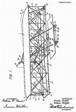
Figure 1, Isometric View.

Figure 2, Top View.
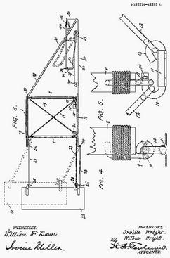
Figures 3,4, and 5 -- Side View and details.
|

