|

The
1905
Wright
Flyer III

 Up
Up
 The Real McCoy

(You are here.)

  Need
to Need
to
find your
bearings?
Try
these
navigation aids:
If
this is your first
visit, please stop by:
Something
to share?
Please:
|
|
Available in Française, Español, Português, Deutsch, Россию,
中文,
日本, and others.
 n
preparation for building a flying copy of the 1905 Wright Flyer III, we took a trip to
the Wright Brothers Aviation Center at Carillon Historic Park in Dayton, Ohio to
inspect the real McCoy -- the original 1905 aircraft, restored. The aircraft is displayed in a specially designed
building, Wright Hall. As you walk in, it's slightly
below you in a huge well or "pit." The curatorial staff, Mary Mathews
and Jean Palarmo, kindly let us into the pit to take close-up photos. This was no small favor,
since this aircraft has been dubbed a national treasure by an act of Congress.
It's also the only aircraft to be designated as a National Historic
Landmark. It is indeed a treasure. Charles Gibbs-Smith, a prominent aviation historian, dubbed this restored airplane
the most valuable aviation artifact anywhere because it was the
first practical airplane, capable of taking off
under its own power, navigating to a pre-determined location, and -- as
Wilbur Wright so succinctly put it -- "landing without wrecking." n
preparation for building a flying copy of the 1905 Wright Flyer III, we took a trip to
the Wright Brothers Aviation Center at Carillon Historic Park in Dayton, Ohio to
inspect the real McCoy -- the original 1905 aircraft, restored. The aircraft is displayed in a specially designed
building, Wright Hall. As you walk in, it's slightly
below you in a huge well or "pit." The curatorial staff, Mary Mathews
and Jean Palarmo, kindly let us into the pit to take close-up photos. This was no small favor,
since this aircraft has been dubbed a national treasure by an act of Congress.
It's also the only aircraft to be designated as a National Historic
Landmark. It is indeed a treasure. Charles Gibbs-Smith, a prominent aviation historian, dubbed this restored airplane
the most valuable aviation artifact anywhere because it was the
first practical airplane, capable of taking off
under its own power, navigating to a pre-determined location, and -- as
Wilbur Wright so succinctly put it -- "landing without wrecking."
This treasure was almost lost to us. The Wrights last flew it in
1908 at Kitty Hawk making the world's first
passenger flights. But Wilbur had difficulty with the
unfamiliar controls and wrecked the airplane, so the Wrights
abandoned it in their shed. It remained there until 1914 when Zenas
Crane obtained Orville's permission to salvage it for the Berkshire
Museum in Pittsfield, MS. The Berkshire Museum, however, never
touched the wreck and it remained in storage until 1946 when Edward
Deeds began building Carillon Historic Park. Deeds asked Orville for
an airplane; Orville asked the Berkshire Museum to return the Flyer.
Harvey P. Geyer, who had once worked for the Wright Company and
himself an accomplished inventor, headed the restoration under the supervision
of Orville Wright. Louis P. Christman worked with Orville on the
engineering drawings.
The restored aircraft was unveiled in 1950. It had been "lying
in state" for half a century when we were allowed into the pit. For us, this was
a marvelous opportunity to get nose to
nose with the craftsmanship of the Wright brothers, marvel at their attention to
detail, and explore their innovative, no-nonsense approach to engineering. We
thought you might like to the share this adventure, so here, with many thanks to
Carillon Historic Park, is a photographic walk-around of the
original 1905 Wright Flyer III.
|
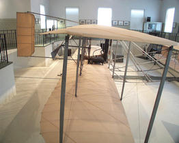
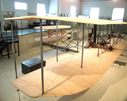
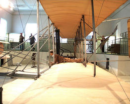
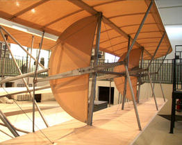
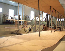
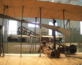
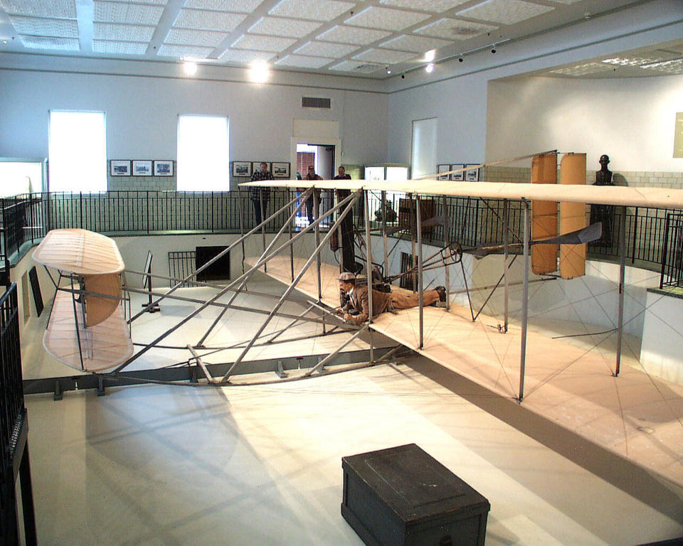
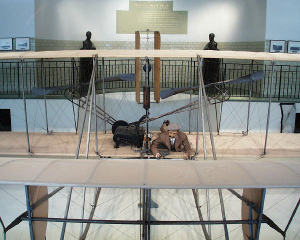
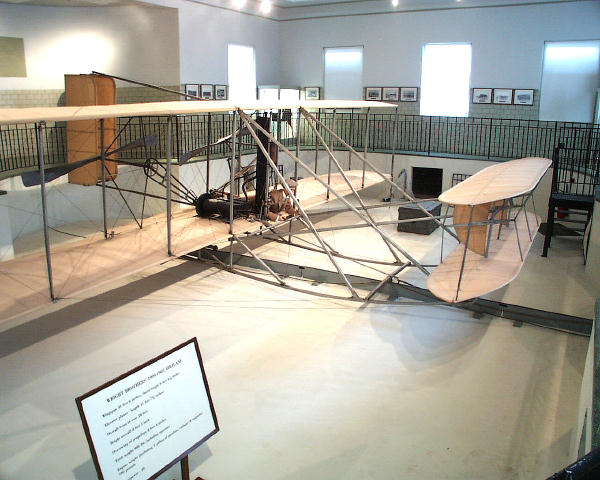
Let's begin with a walk around the "Pit" in Wright
Hall, where the 1905 Flyer III is displayed. This is
the scene that greets you as you enter from the east.
|
Move to your right and follow the walkway that runs
around the pit.
The Flyer rests on a section of the launch rail.
|
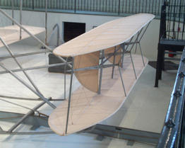
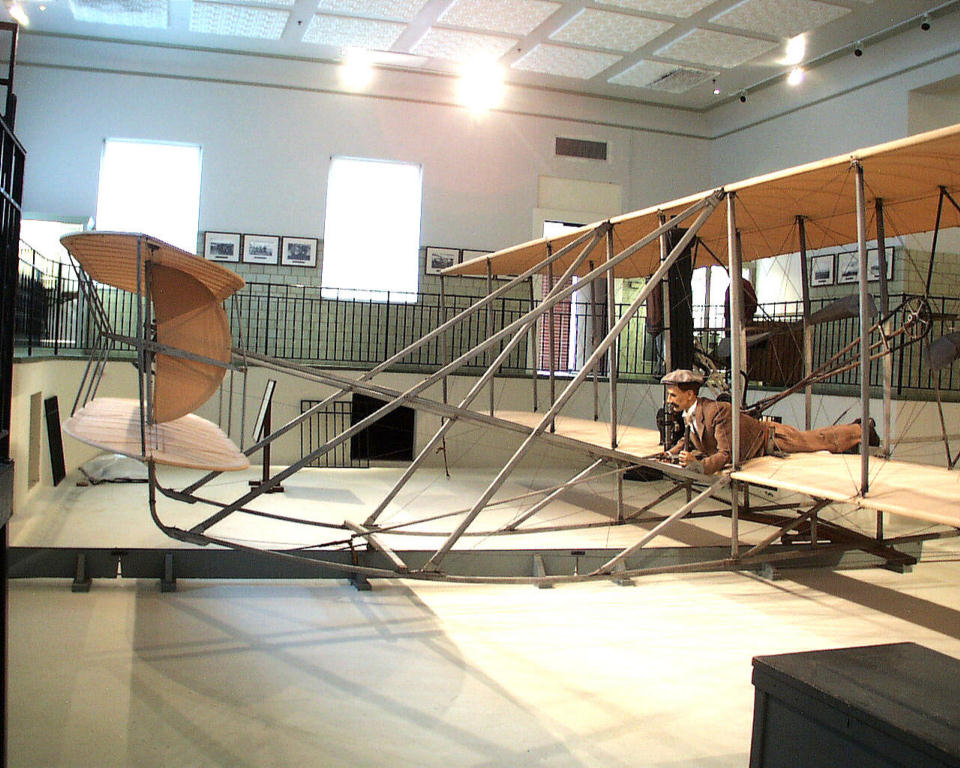
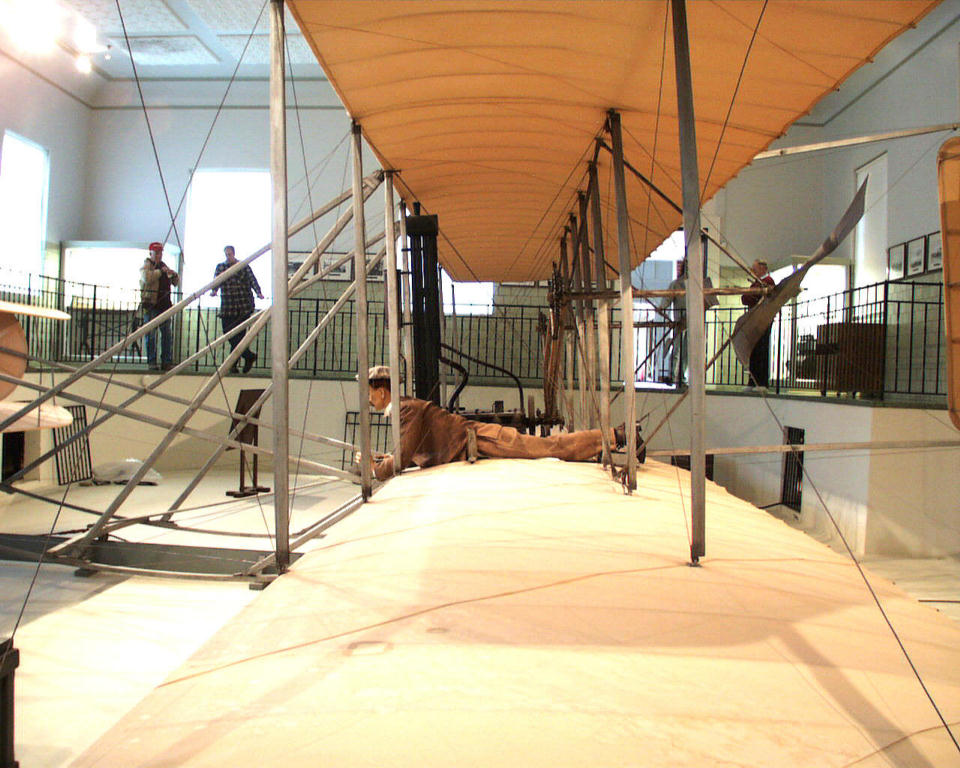
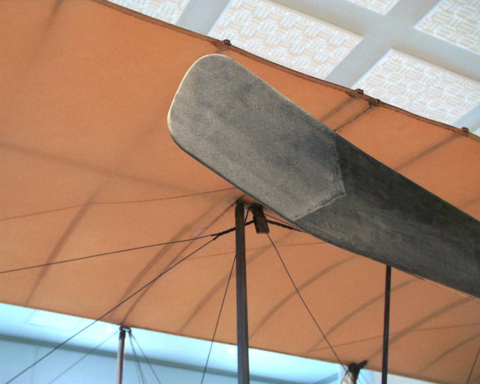
The most distinctive feature of this airplane is the prominent forward
elevator or "canard" out ahead of the wings. This is almost as large
as the the Wrights' first man-carrying glider.
|
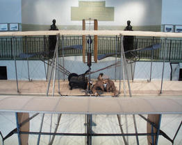
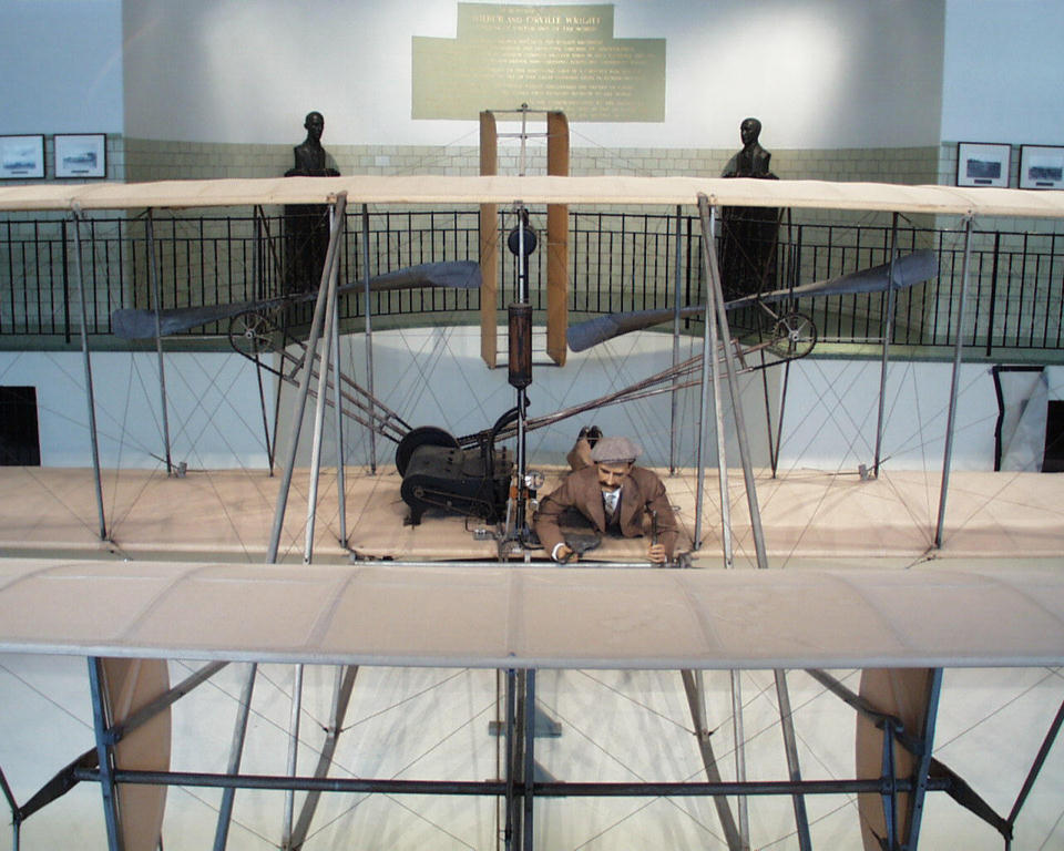
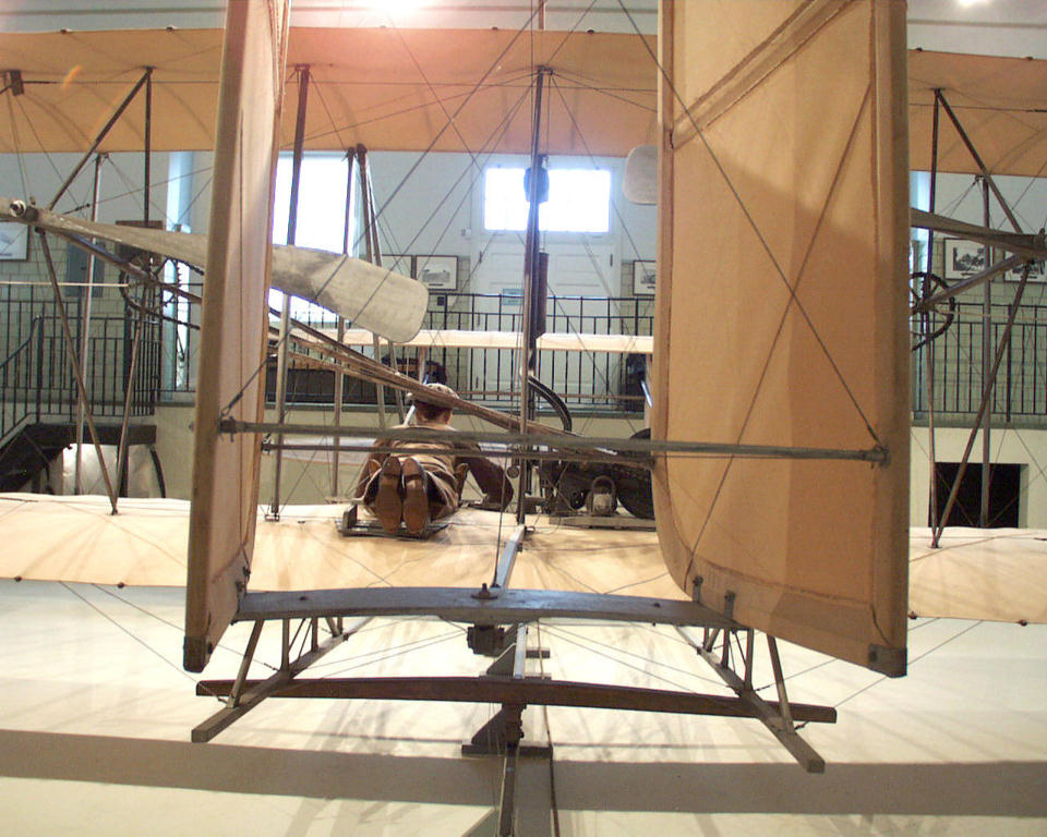
Here's the Flyer as it appears head-on. At the back of the hall, you
can see the bronze busts of Wilbur and Orville Wright.
|

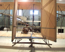
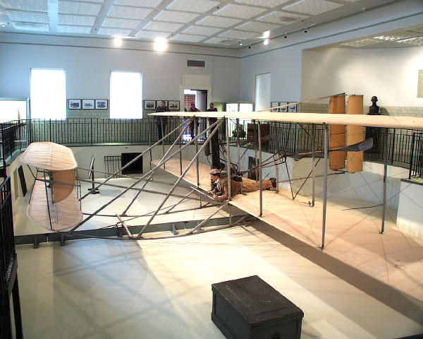
Continuing around, here's a diagonal view from the
front left. The large green wooden box in front of the left wing is
the Wrights' tool chest. They kept this at Huffman Prairie when they
were developing the Flyer, and it may have also traveled with them
to and from Kitty Hawk.
|
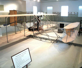
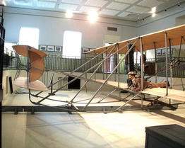
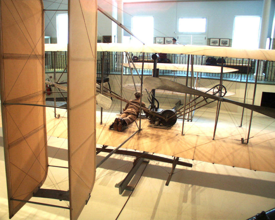
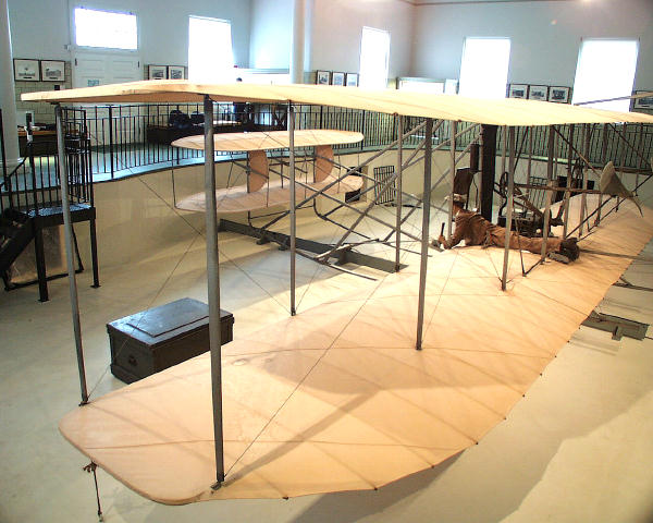
A little further on, here's an overview of the Flyer from the back
left. You get a real sense of just how big this aircraft is -- 40
feet from wing tip to wing tip and 27 feet from nose to tail.
|
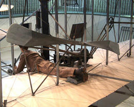
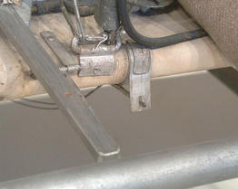
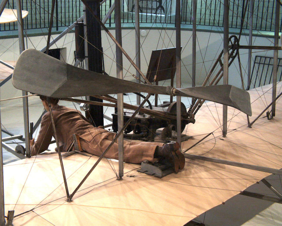
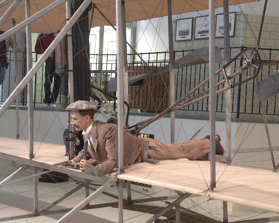
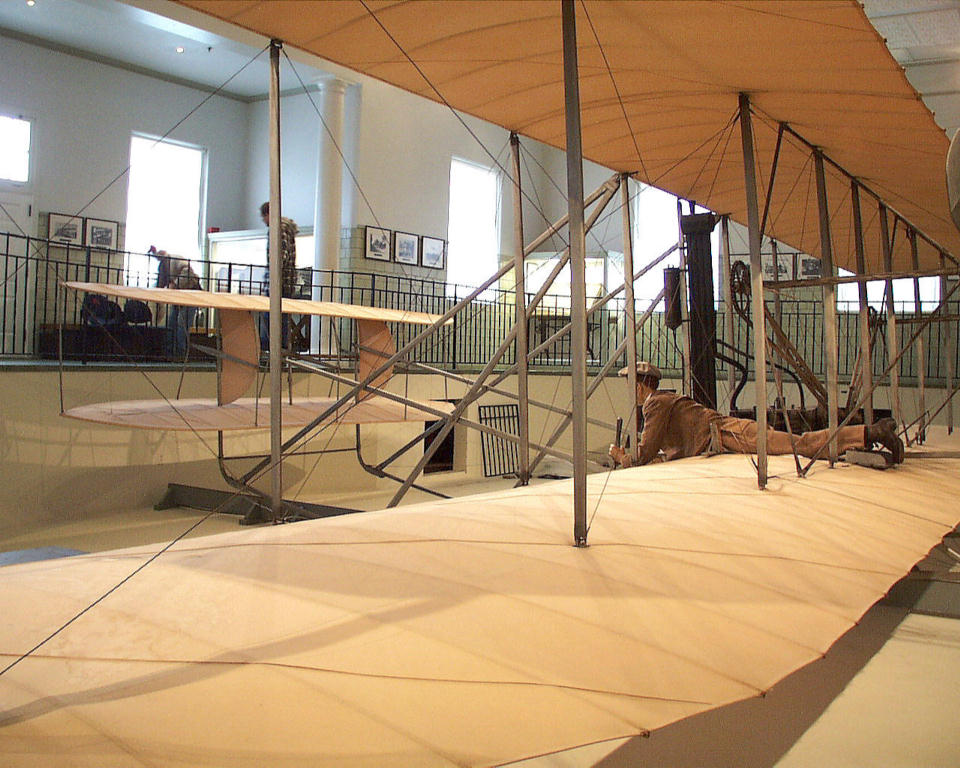
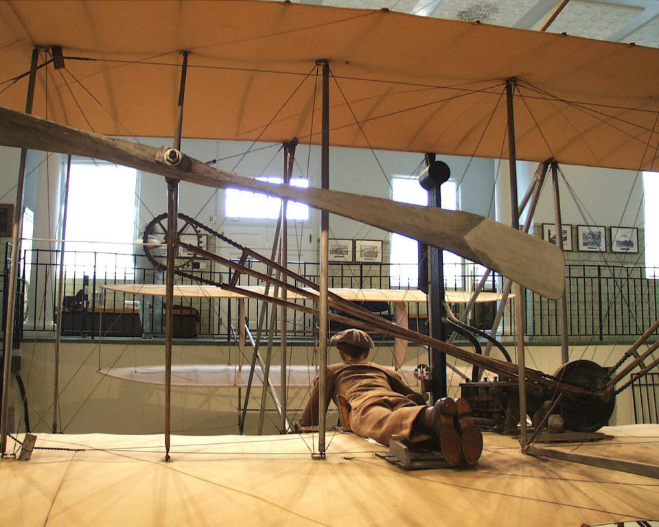
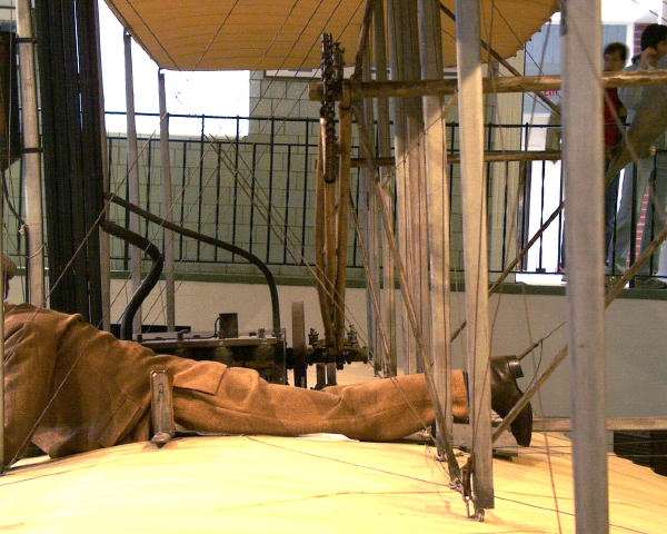
A close-up view of the Flyer's cockpit from behind and to the left.
The Flyer III was the last Wright aircraft on which the brothers lay
prone to fly it. Note that the tubes that enclose the drive chain on
the left side are crossed. The propellers rotate in opposite
directions.
|
Another view of the chain tubes at the rear of the
Flyer. The Wright made the propellers contra-rotate so the
centrifugal and coriolis forces generated by the props would cancel
each other out and not pull the aircraft to one side.
|
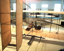
As we walk down the stairs that lead from the walkway into the pit,
our perspective changes. Now the aircraft isn't just big; it's over
8 feet tall.
|
Looking down the length of the wing from the left. This what the
brothers or their mechanic Charley Taylor must have seen running
along at the wing tip as the Flyer launched.
|

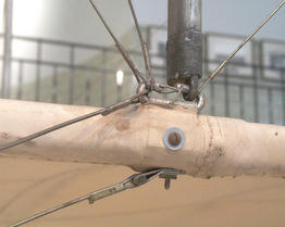
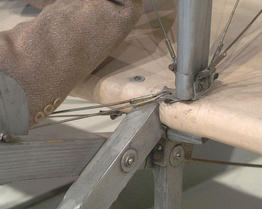
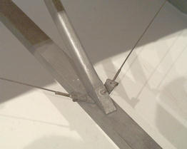
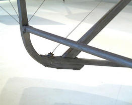
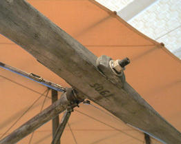
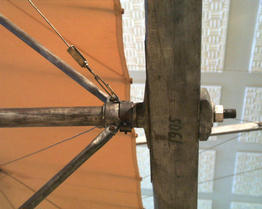
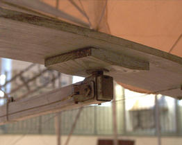
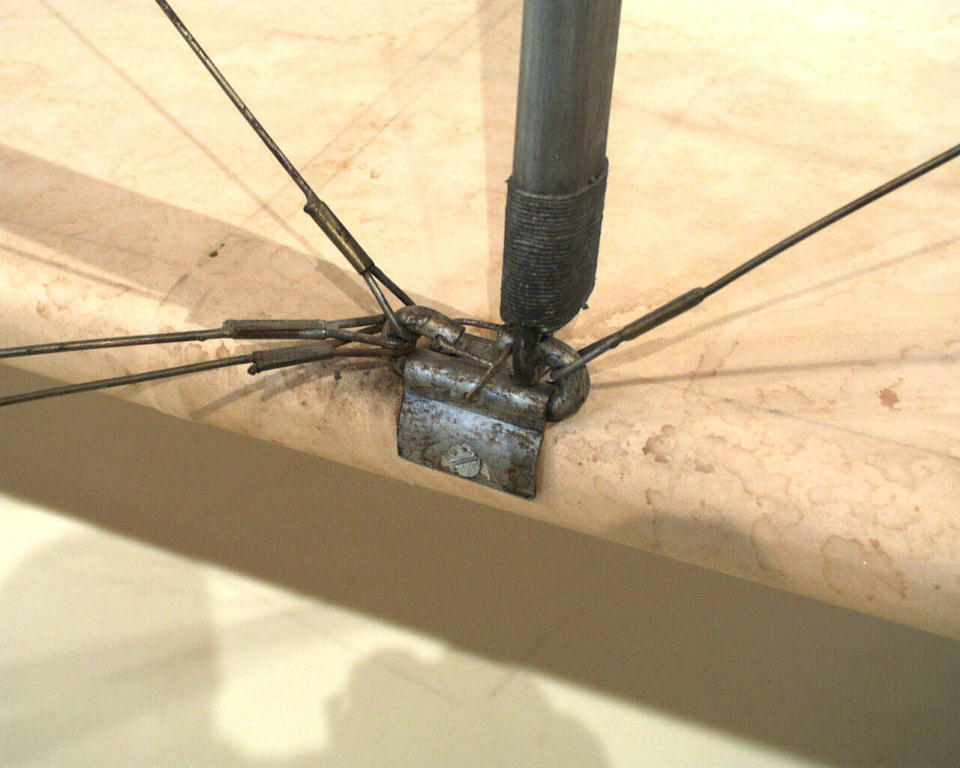
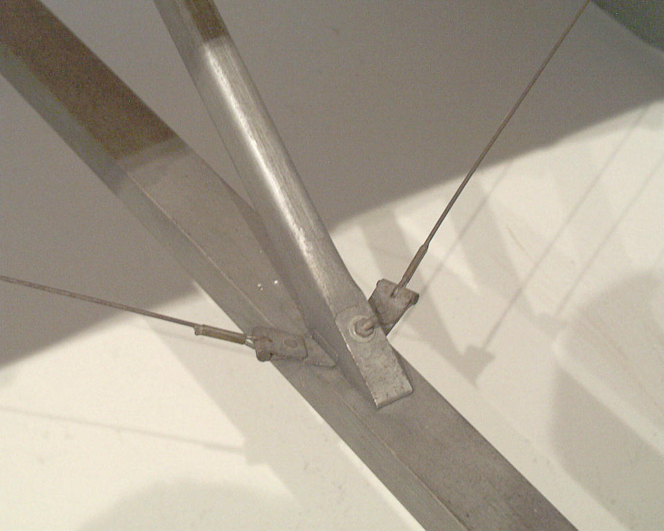
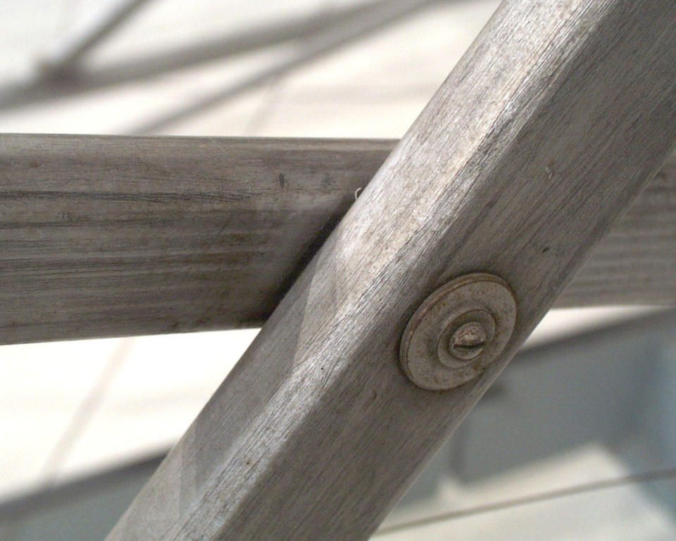
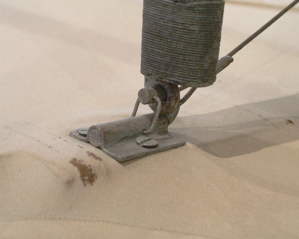
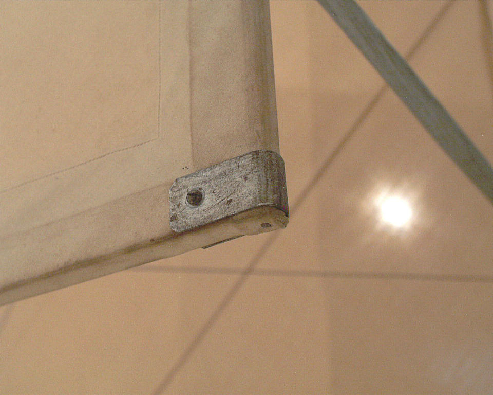
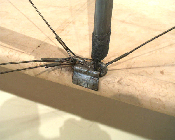
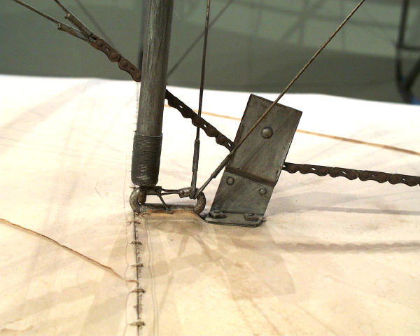
A view of a strut fitting, joining the lower wing to
a vertical strut. These were in fact hinges that allowed the wings
to move when the pilot warped them.
|
Closer still to the strut fitting. Note how the Wrights "safety wired"
the flitting so the strut and the rigging would not slip off.
|
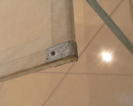
Most of these fitting are simply screwed to the wing
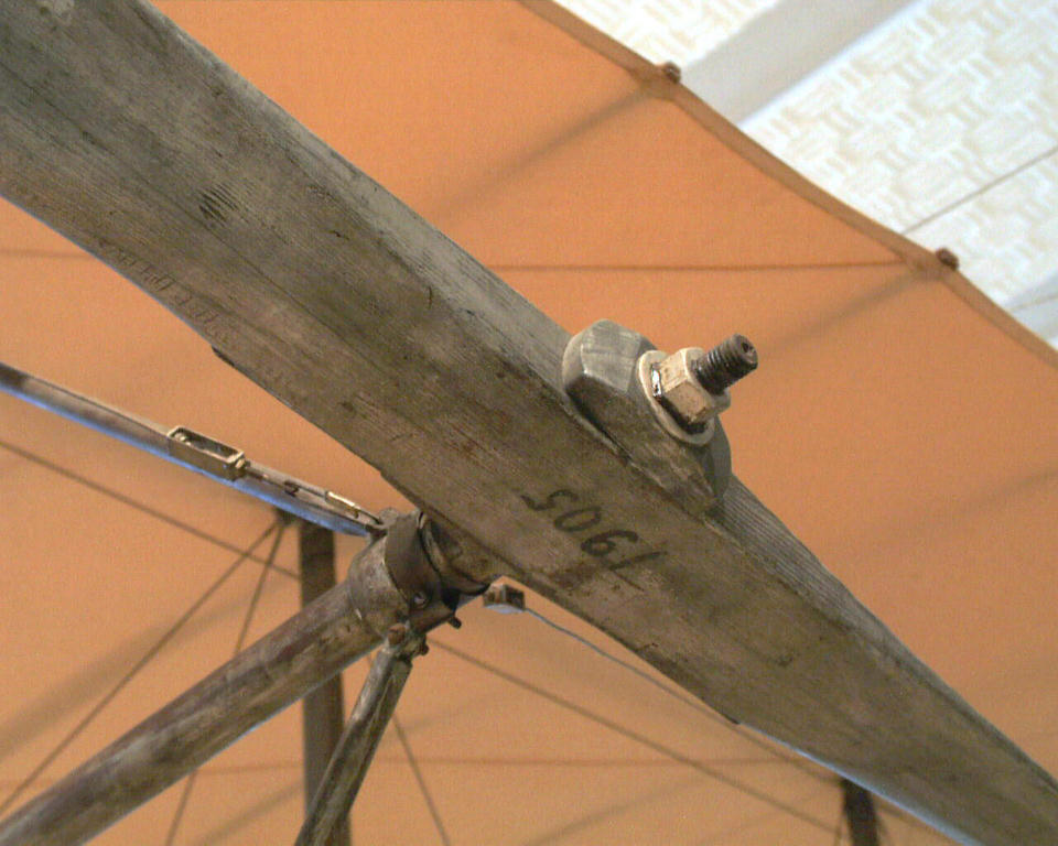
spars. A very few are attached with bolts that go through the spars. |
The wing covering is applied on the "bias" -- the
threads run diagonally across the ribs. Each thread becomes a tiny
brace, greatly increasing the strength of the wings.. |
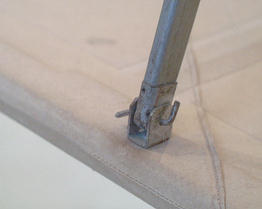
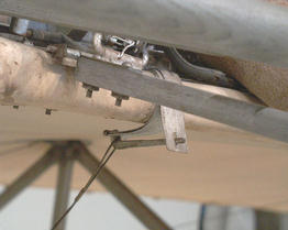
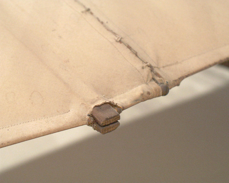
The post and braces that attach the skids to the
Flyer are fitted and screwed to the wings. |
The skids themselves are split at the front of the aircraft, then
joined with this U-shaped fitting. This allowed the Wrights to
easily detach the front skid assemblies when they stored the Flyer.
|
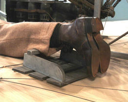
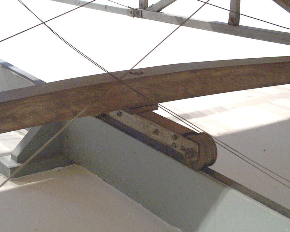
Beneath the wings, the skids rest on a wheeled
carriage or "truck." This truck carries the aircraft as it rolls
down the launch rail, but is left behind when the Flyer takes off..
|
A closer view of the wheeled truck and the launch rail.
|
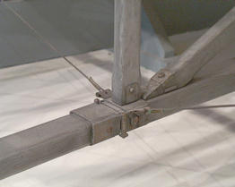
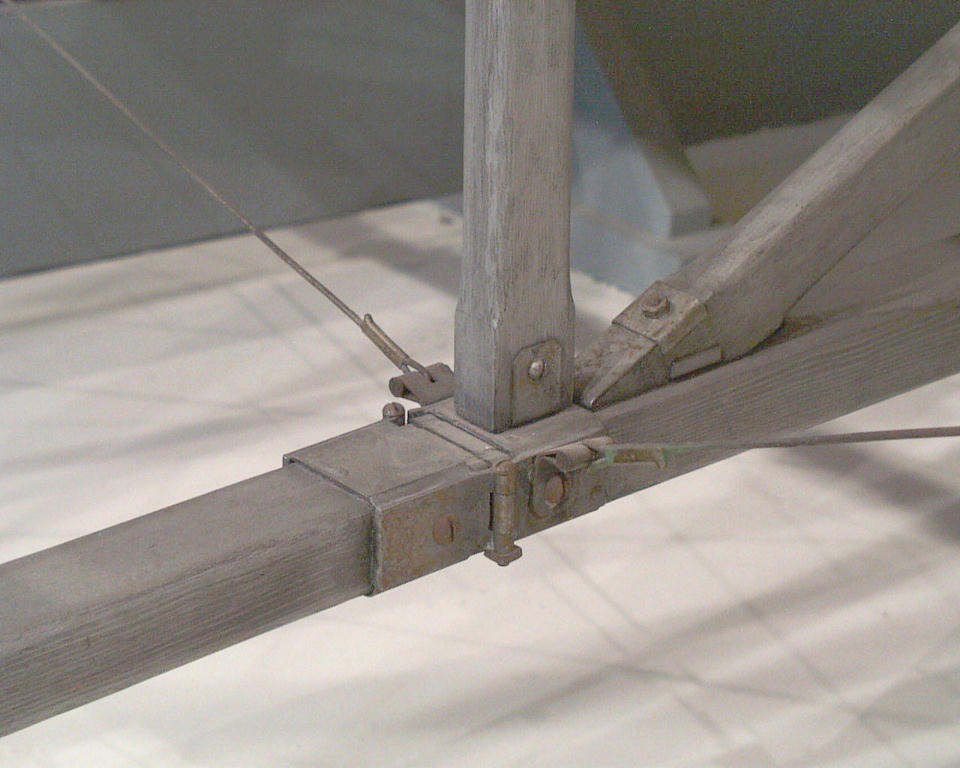
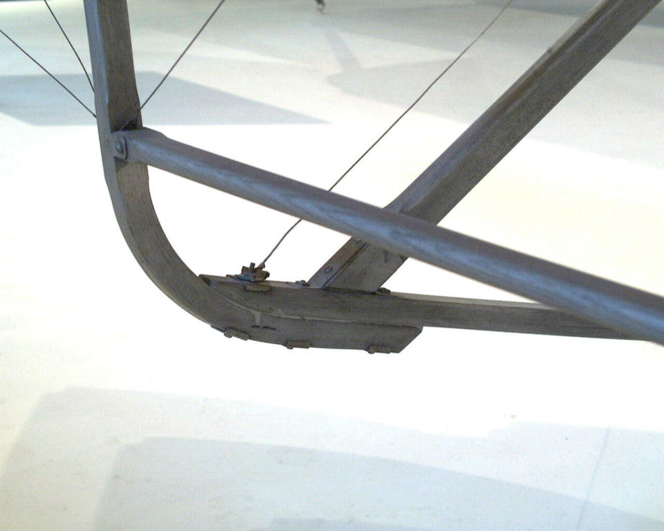
Just in front of the wings, a brace runs from the
leading edge of the lower wing and joins the skid just as it begins
to curve upwards.
|
.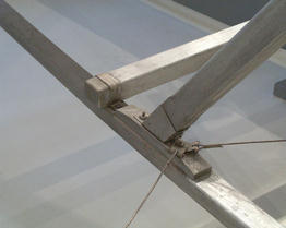
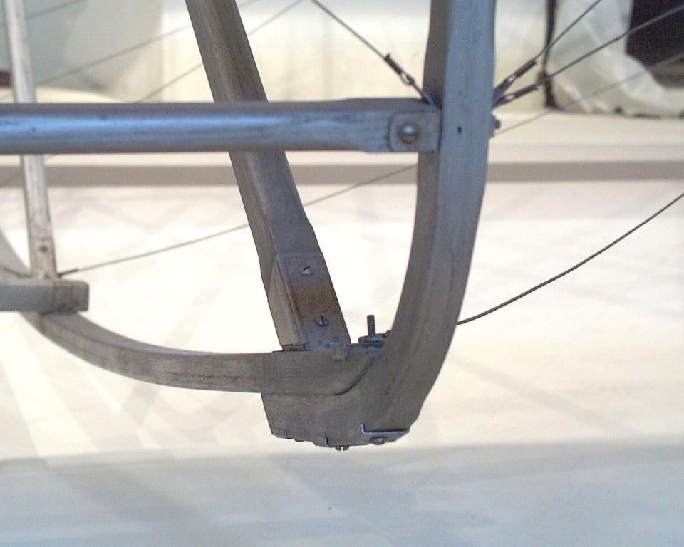
Following the curved portion of the skid forward, another diagonal
brace joins it midway. Just forward of this brace, a horizontal tie
bar joins the left and right skids.
|
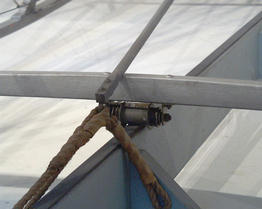
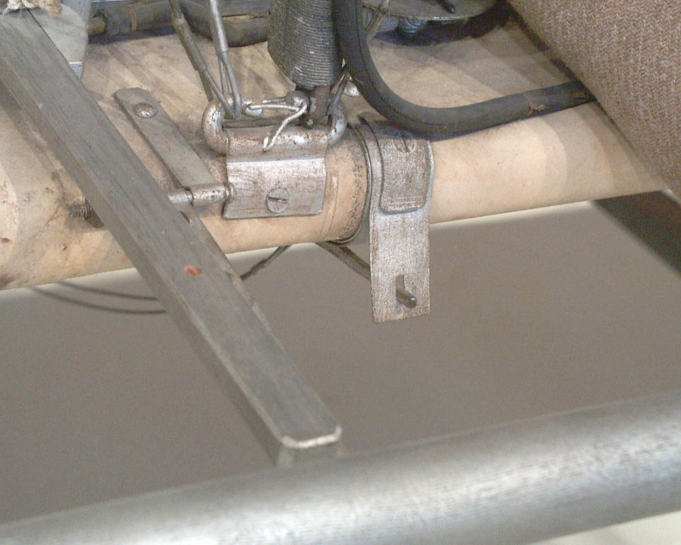
This tie bar mounts a roller that rides the rail
during a launch, keeping the Flyer pointed forward. This roller is
actually an old bicycle wheel hub.
|
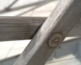
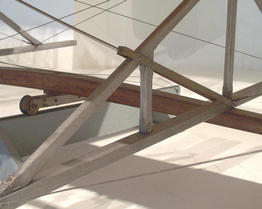
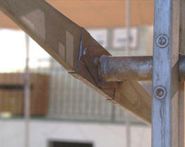
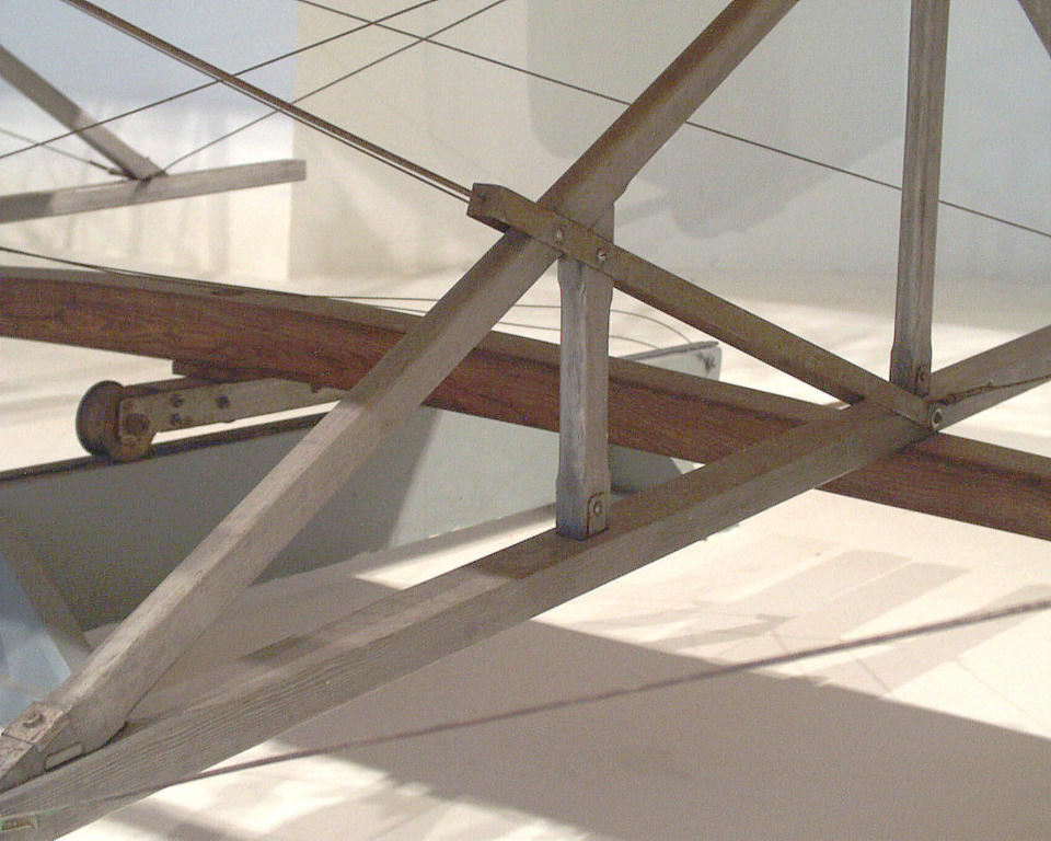
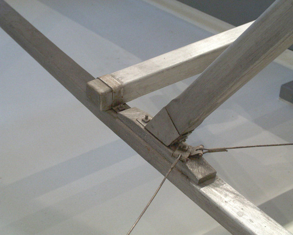
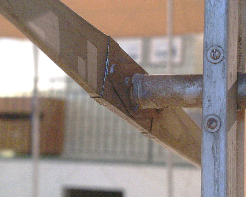
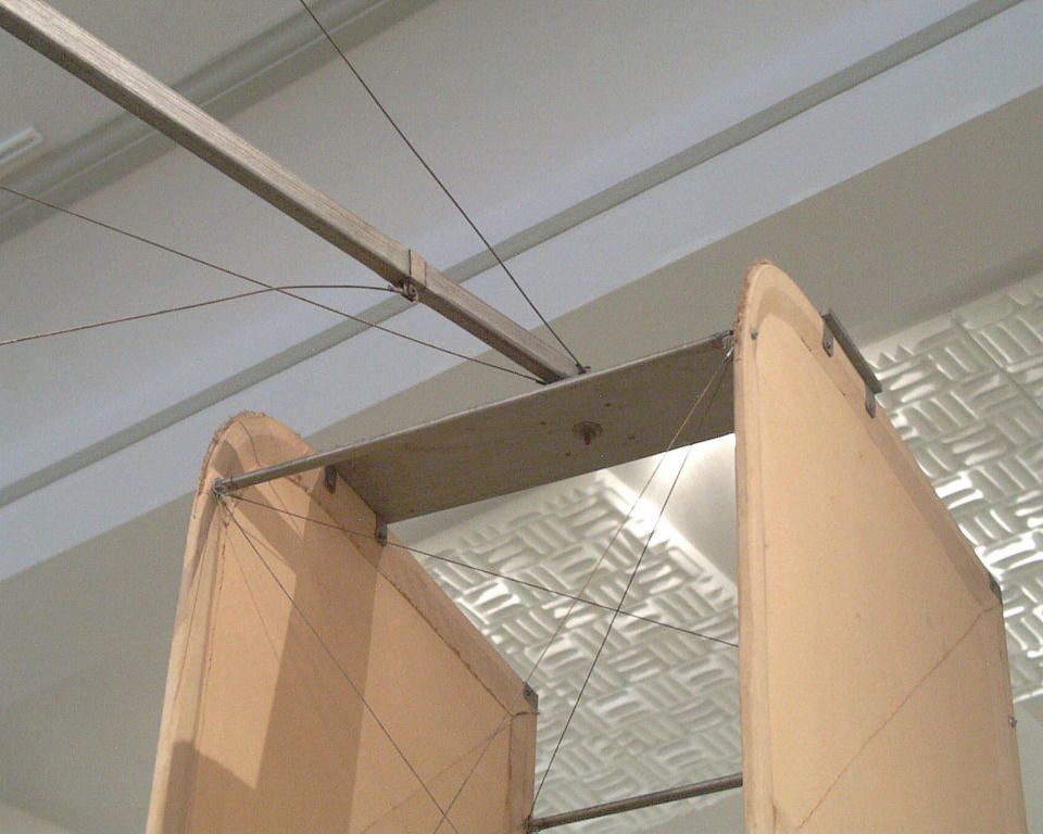
Horizontal "outriggers" run from the leading edge of the wing to
vertical posts that support the elevator. Where an outrigger crosses
a brace, the two parts are bolted together,
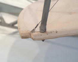
|

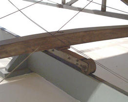
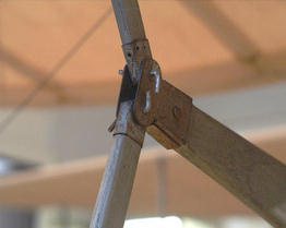
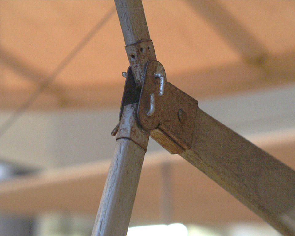
The bottom portion of the elevator support post is curved and fitted
to the skid. Another diagonal brace, running from the leading edge
of the top wing, joins the skid and the post.
|
Another view of the juncture between the skid, front brace, and
elevator support post. A small horizontal tie bar joints the posts.
|
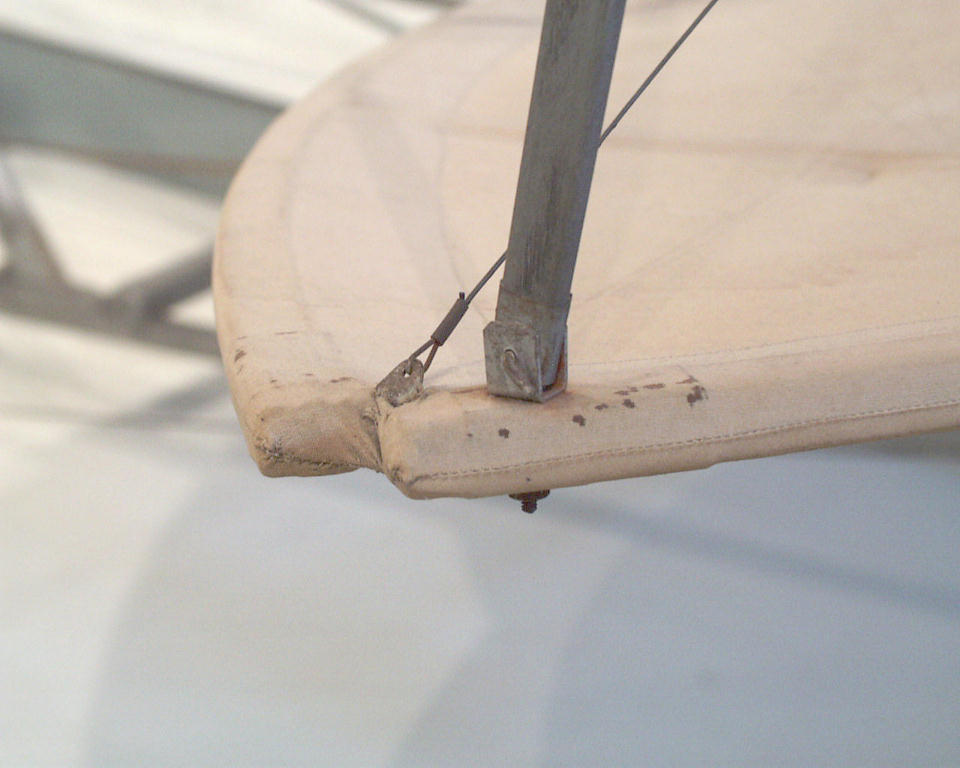
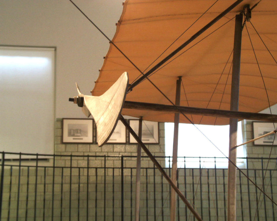
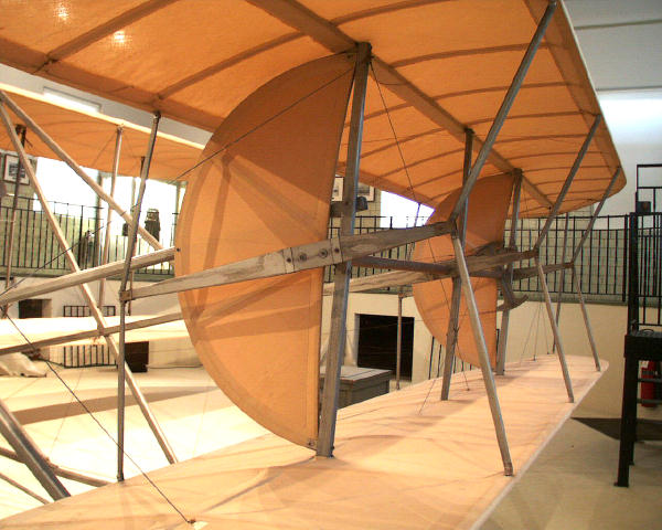
A view of the elevator and the mechanism that adjusts the angle of
the top and bottom control surfaces. The semi-circular air foils,
called "blinkers" by the Wright brothers, help to stabilize the
Flyer in a turn.
|

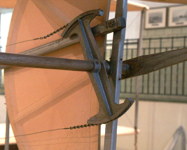
The chains and wires lead to the elevator control in the cockpit.
Moving this control rotates the dumbbell-shaped casting and the
horizontal shaft to which it is attached.
|
As the shaft rotates, it cause three horizontal control arms -- one
at each end and one in the middle of the shaft -- to rotate as well.
|
Each end of each control arm is a double pivot that attaches the arm
to to vertical actuators running to the top and bottom control
surfaces.
|
Each actuator arm is attached to a control surface at the leading or
trailing edge with another pivot. As the pilot moves the elevator
control , this motion is transferred through the wires, dumbbell,
shaft, and arms to the control surfaces, changing their angle up or
down.
|
You can't see the hardware because it is covered in cloth, but each
elevator control surface is hinged in the middle. As the surface
moves changes its angle, it also changes camber, curving up or down.
|
Like the biplane wings, the biplane elevator is rigged with wires
running diagonally to create a strong truss. Although the elevator
surfaces can pivot, changing angle and camber, the assembly is rigid
from side to side.
|

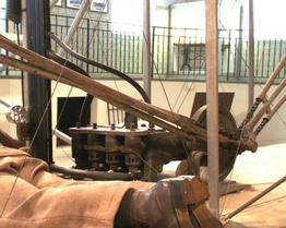
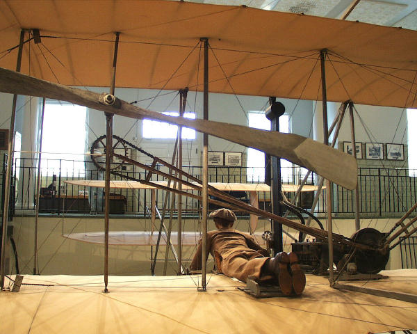
The pilot, engine, and drive train occupy four "bays" in the center
of the aircraft. (A bay is a space between two struts.) These four
bays are completely rigid, the wings don't warp in this area.
|
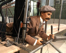
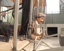
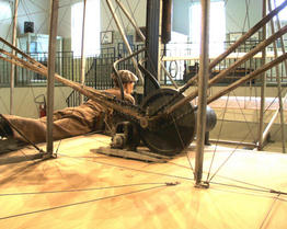
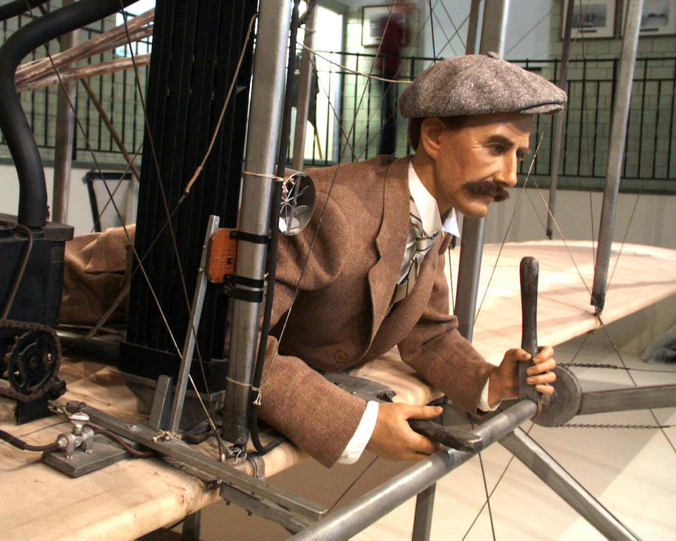
The cockpit bay includes the pilot, manual controls for roll, pitch
and yaw, and a rudimentary set of flight instruments.
|
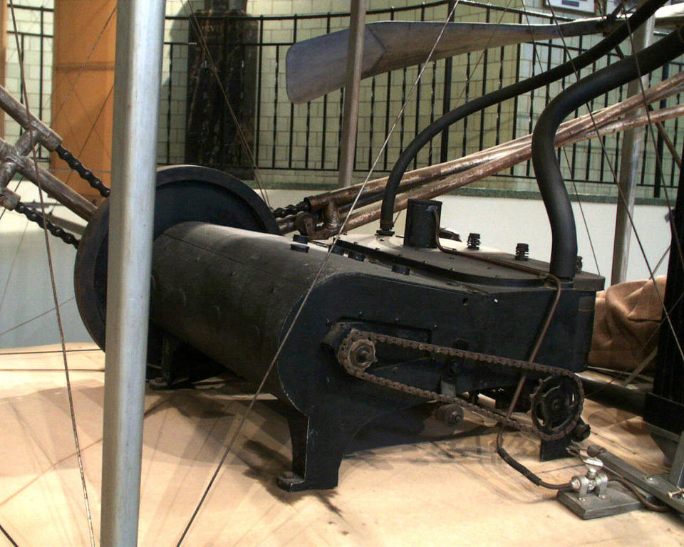
The engine bay is just to the right of the pilot. The red hot
combustion chambers are just 11 inches from the pilot's right side.
|

The engine has four cylinders, make-and-break ignition (no spark
plugs), and develops 25 horsepower. The small chain in front runs a
camshaft, opening and closing the exhaust valves.
|
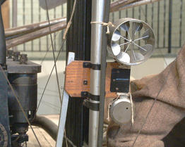
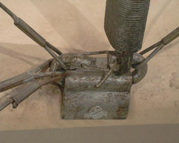
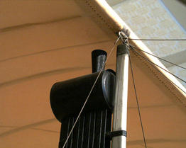
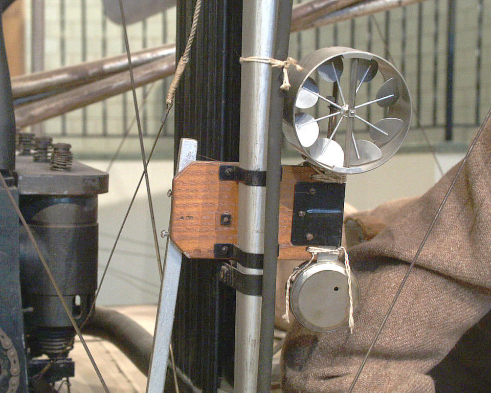
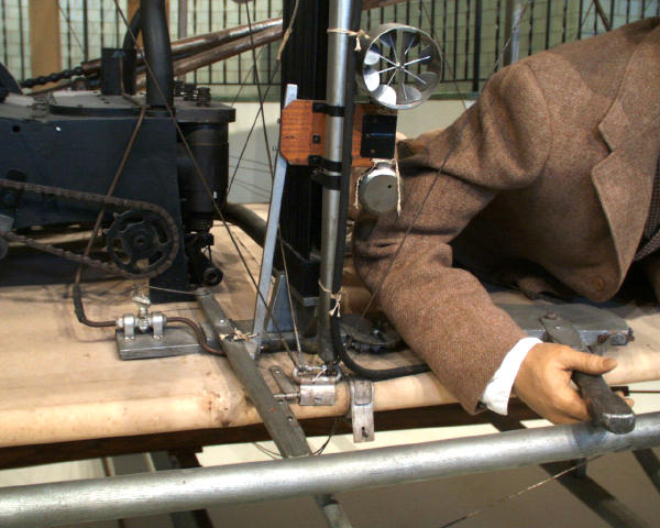
The Richard Anemometer attached to the front center strut serves as
a flight recorder, recording the time aloft and distance flown
through the air.
|

Once the aircraft has landed, the pilot pulls on the lever to his
right, stopping the wind vanes and stopwatch incorporated into the
anemometer.
|

That same action (pulling the lever) closes the valve that feeds gas
to the engine, stopping it. The pilot can also push down on a lever
that opens all the exhaust valves. This too will stop the engine by
releasing the compression.
|
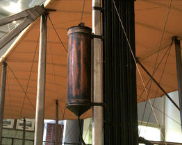
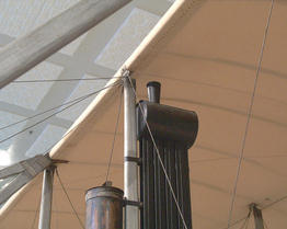
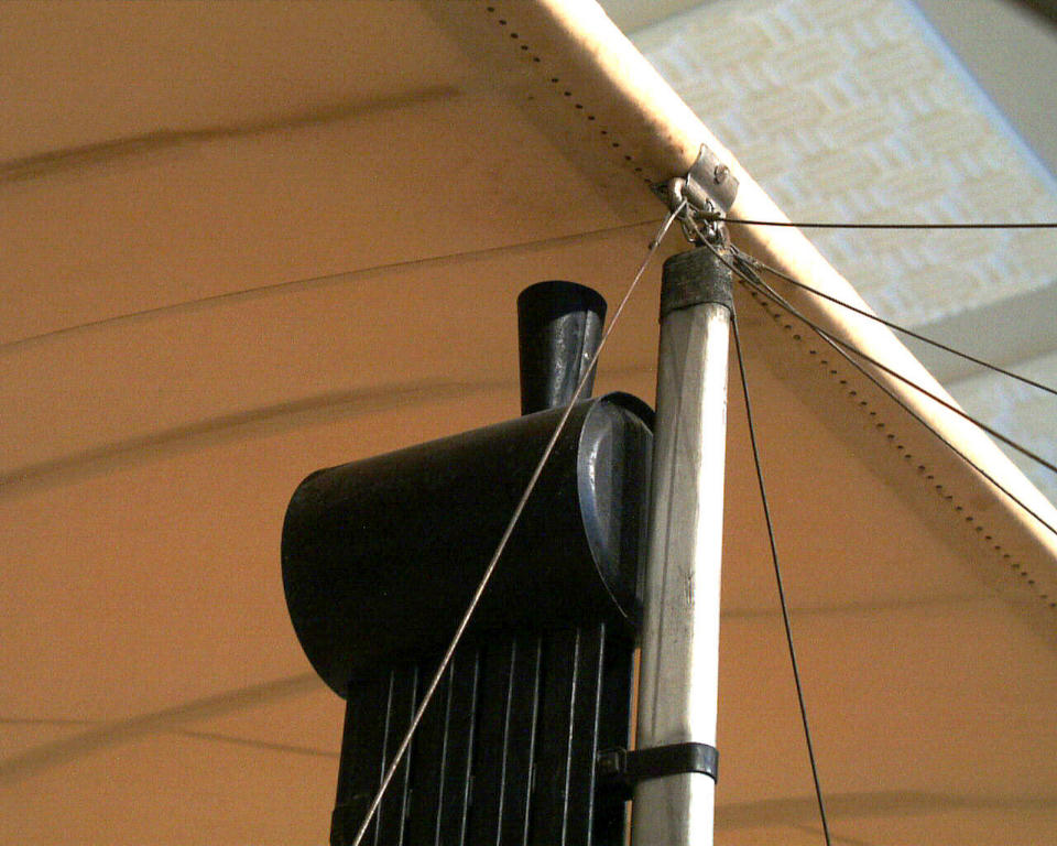
Just above the anemometer is the gas tank. The Wrights carried
enough gasoline to fly for a little over half an hour.
|
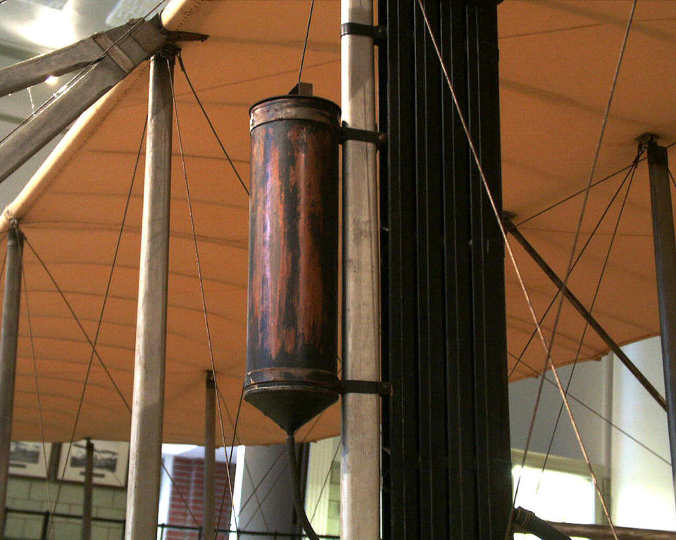
Near the top of the center strut is the reservoir for the radiator.
There is no radiator cap; the steam is allowed to escape without
building up pressure.
|
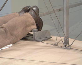
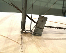
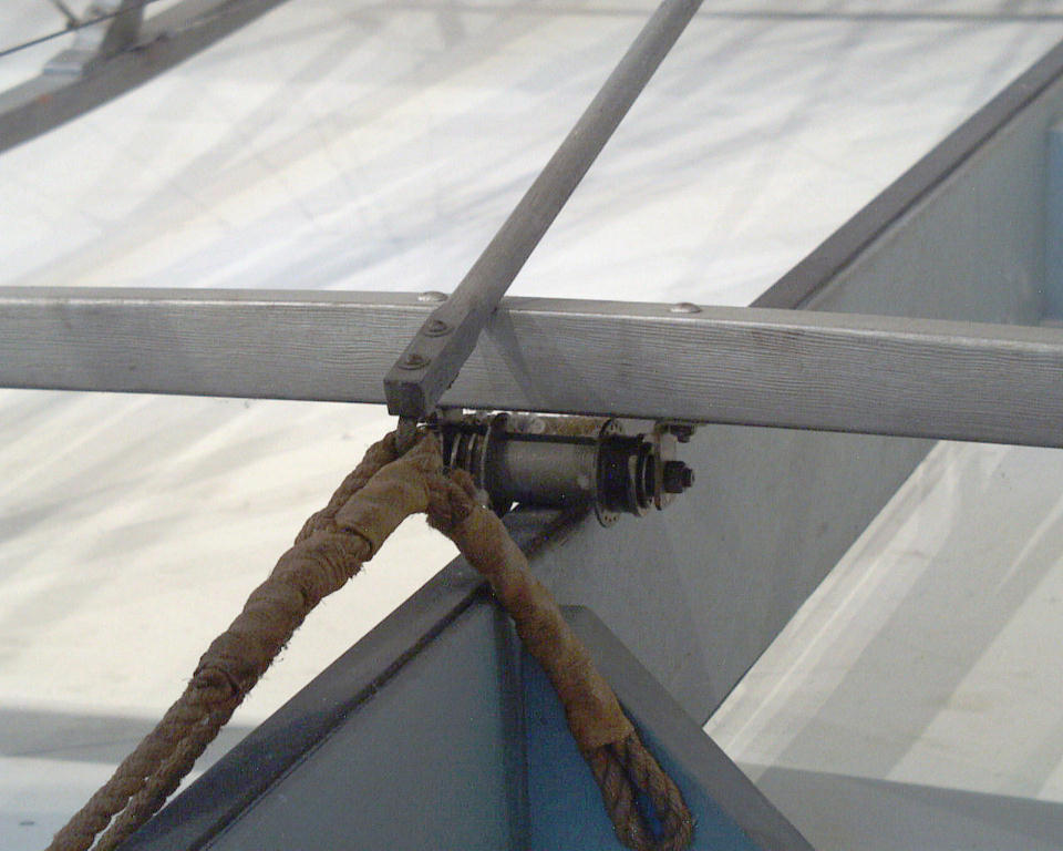
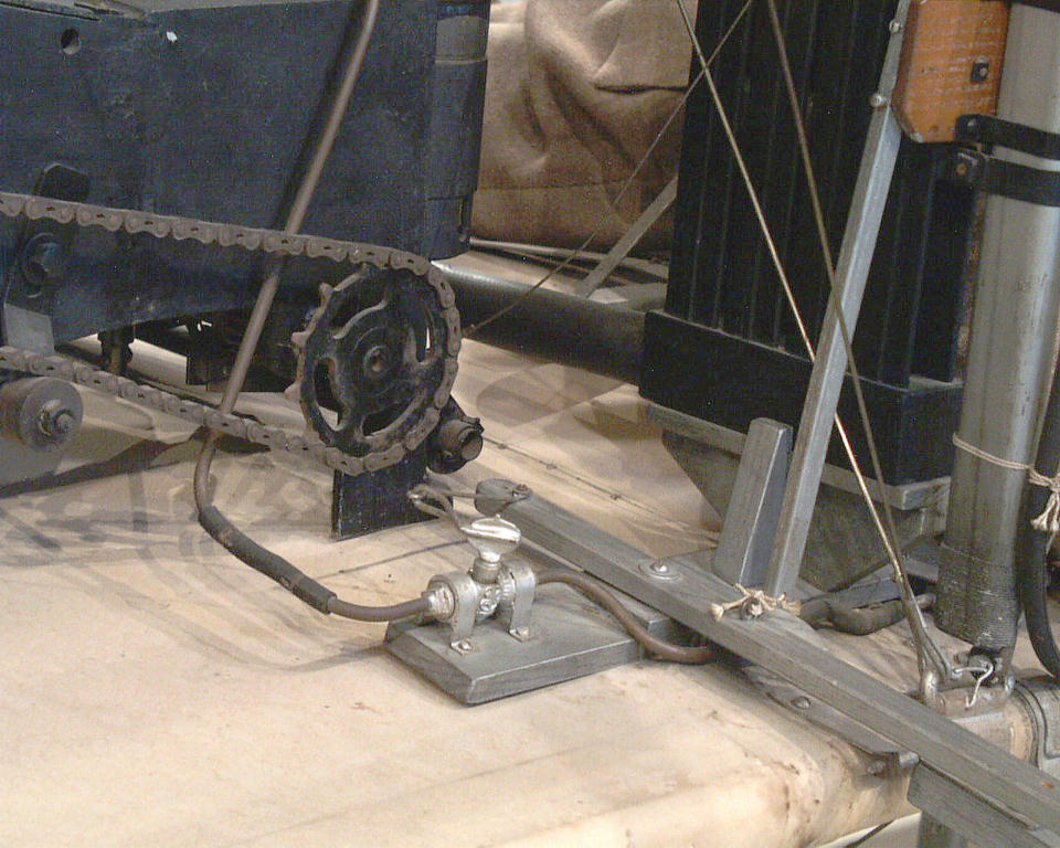
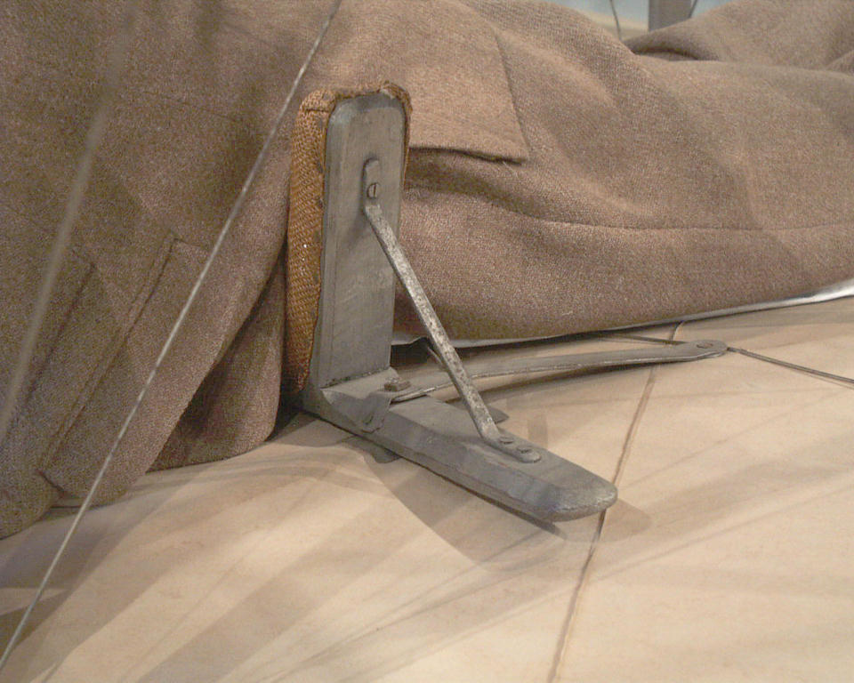
Just to the right of the center strut, mounted to the bottom wing,
is the release latch. A cable was hooked to this latch that
restrained the Flyer and kept it from rolling forward.
|
When it was time to take off, the pilot reached down and pulled
forward on the metal latch. The latch arm pivoted backwards, the
cable dropped, and the Flyer began its take-off roll.
|
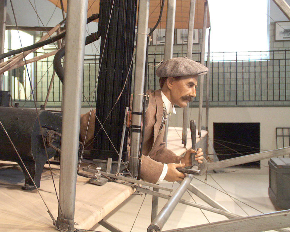
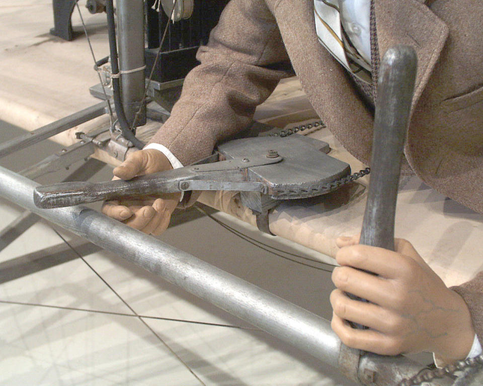
At the pilot's right is a horizontal lever that controls the rudder
and yaws the Flyer right and left. To his left is a vertical lever
that controls the elevator, pitching the nose up and down.
|
The elevator control lever is mounted to a horizontal shaft which
turns a pulley. The wires from the elevator (mentioned above) are
attached to this pulley.
|

The pilot's hips rest in a hip cradle. This is the roll control. As
the pilot moves his hips right and left, the cradle pulls on wires
that warp the wings.
|

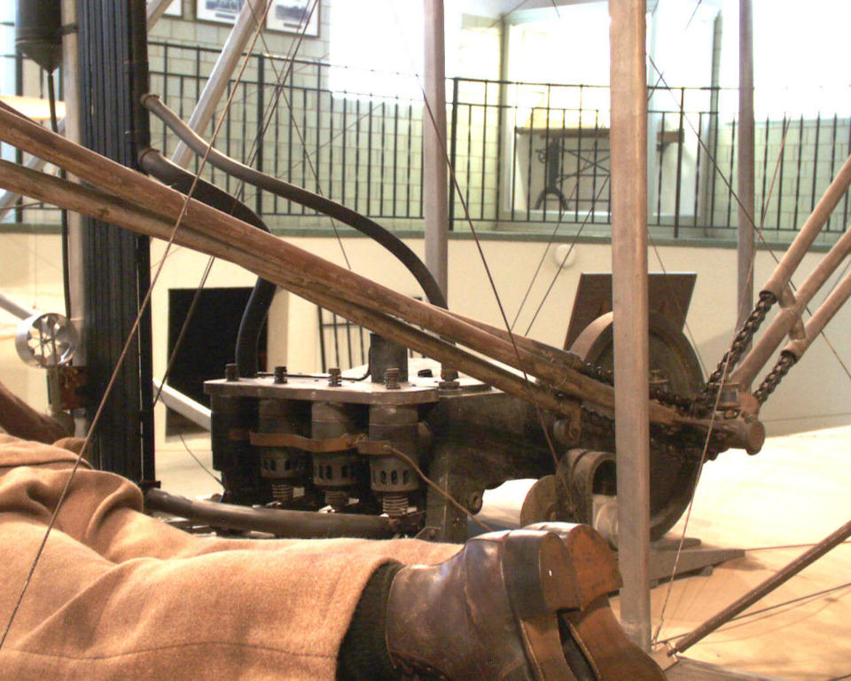
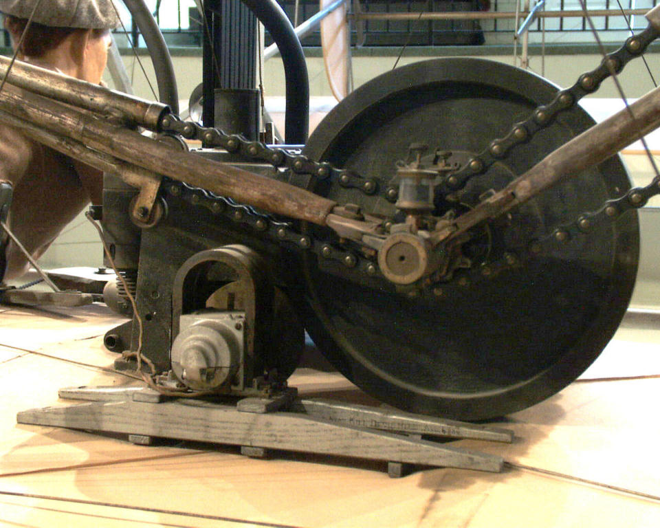
The pilot's legs stretch back under the drive train. The chain drive
stretches out from the engine in two directions to the right and
left propeller drive shafts.
|
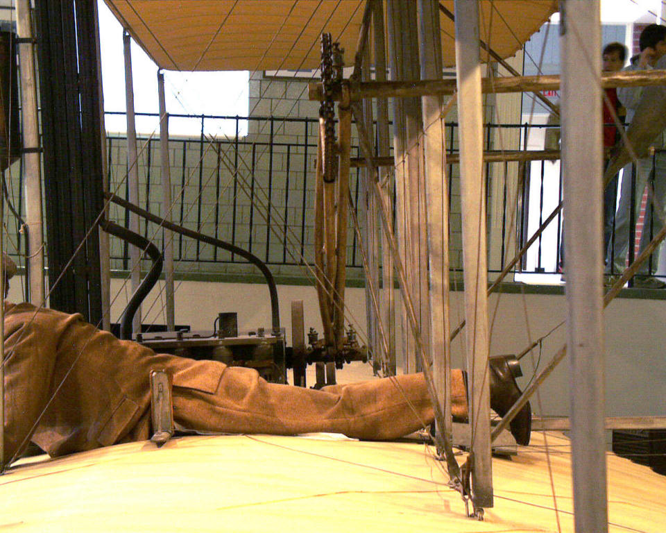
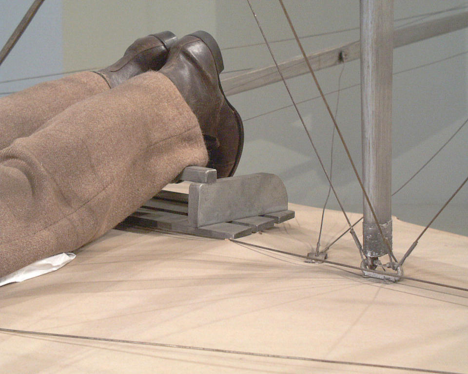
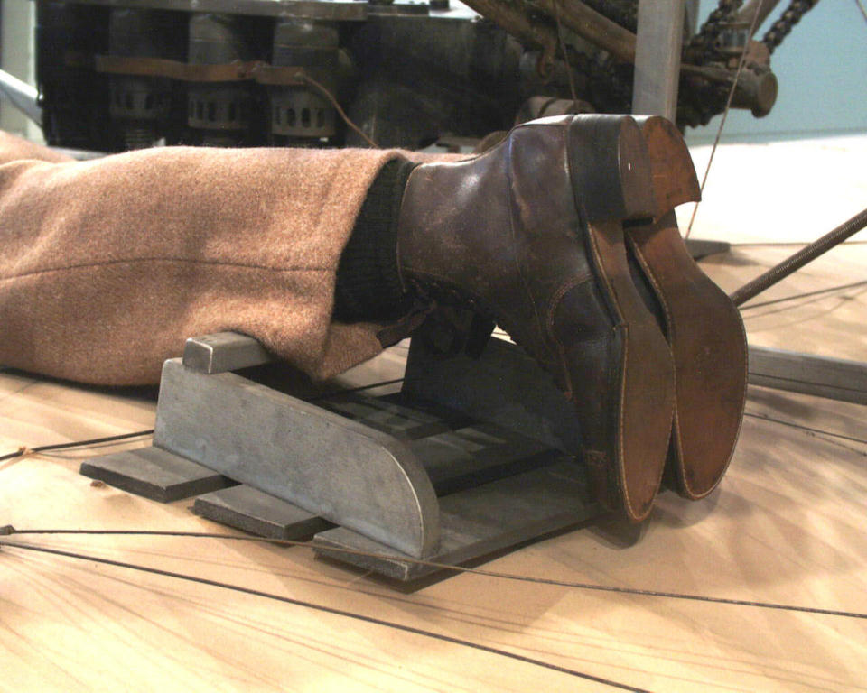
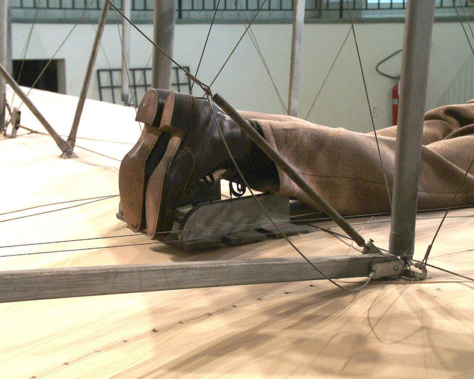
The pilot's feet are positioned in a footrest that is attached to
the rear spar.
|
Moving around to the back of the Flyer, this wide angle shot shows
the portion of the wing that warps when the pilot moves the hip
cradle.
|

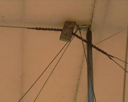
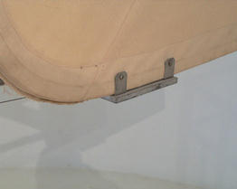
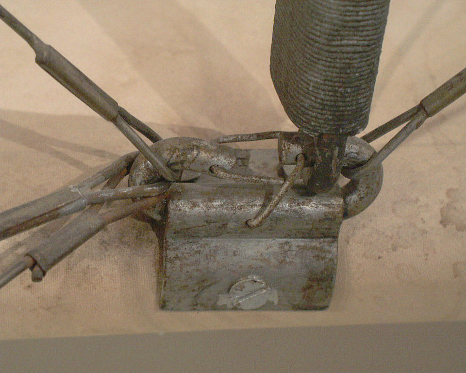
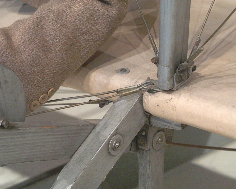
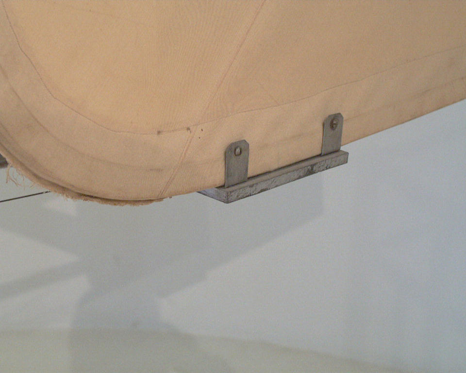
The strut fitting for the rear strut nearest to the left wingtip.
The wire attached to it is a control wire, not structural rigging.
|

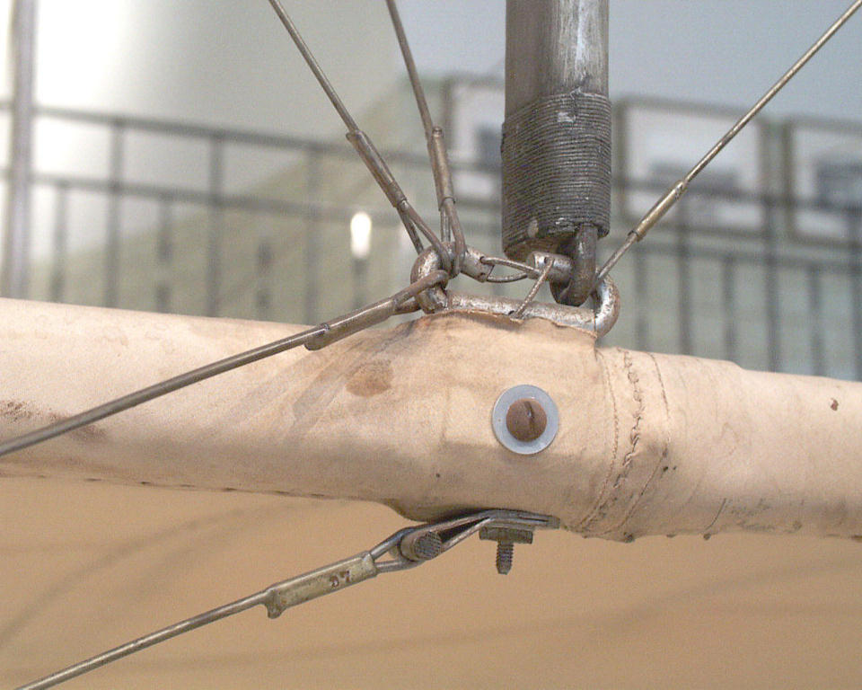
The trailing edge is wire that runs from rib to rib. You can't see
it because it is covered with cloth, but it fits in the notches at
the rib ends. Note the seam that joins wing sections.
|
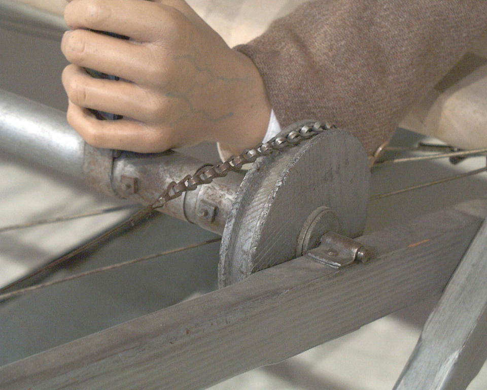
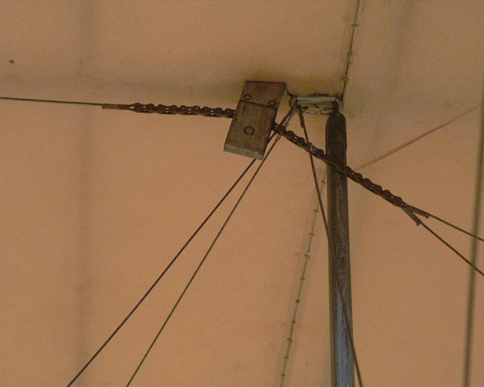
Just inside the seam is the lower control pulley. The control wires
are separated at this point and joined with a chain.
|
The same is true of the upper control pulley and wires. The Wrights
couldn't run a solid wire over a pulley; it would fatigue and break.
So they used bicycle chain at each pulley.
|
Another view of the footrest. The pilot's toes should be hooked
under the bar and each shoe tight against the side boards. This
provided an anchor for the pilot when he moved his hips right and
left.
|
Just over the pilot's legs, you can see the four combustion chambers
on the left side of the engine. These ran exceedingy hot.
|
Looking forward, note how the pilot had to arch his back and hold
his head up to fly. This created enormous physical strain during
long flights.
|
When the engine of the Flyer III was built in 1904, it produced just
16 horsepower. But the Wrights continued to tweak it until by
September 1905, it was producing 24.
|
The engine ran at about 1300 rpm. The small gears on the crankshaft
and the large gears on the propeller shafts reduced this so the
props turned at just 450 rpm.
|
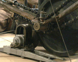
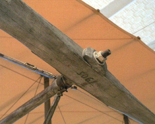
The note on the wooden mount for the magneto says "Found near Kill
Devil Hills Aug 6 '08. This part and many others were recovered from
souvenir hunters on the Outerbanks.
|
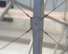
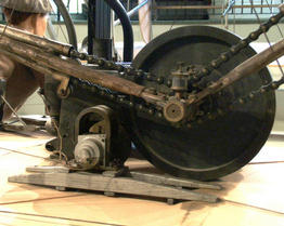
The supporting structure of the drive train consisted of dozens of
metal tubes. As bicycle manufacturers, this was something with which
the Wrights were very familiar.
|
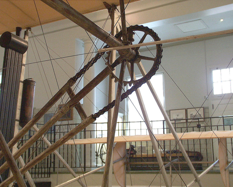
The large gears at the end of the propeller shafts were drilled out
to create spokes. This greatly reduced the weight of this heavy
part.
|
Each propeller is screwed to a flange on the trailing end of its
shaft, then drawn tight with a large nut. The threads are cut so the
nut tightens as the prop turns. This prevents the prop from working
loose.
|
Note the homemade turnbuckles on the bracing wires that hold the
prop shafts in alignment. Of all the hundreds of wires on this
aircraft, this is the only place the Wrights thought to adjust the
tension.
|
The Flyer III was the first to have the Wrights' trademark
"bent-end" props. This unique profile kept the props from distorting
and flattening during flight.
|

The Wrights were the first to guess that props were in fact whirling
wings, Consequently, prop blades are curved -- they have a camber
just like aircraft wings.
|

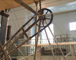
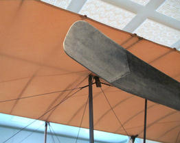
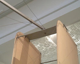
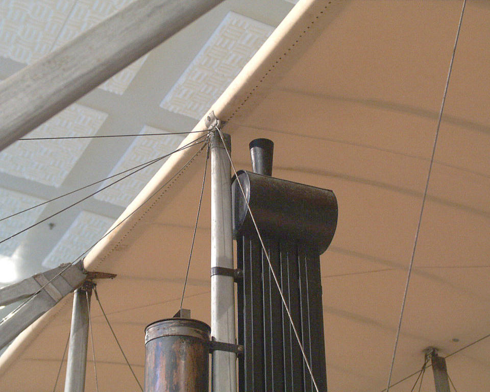
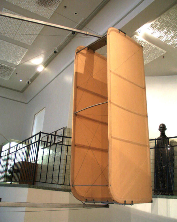
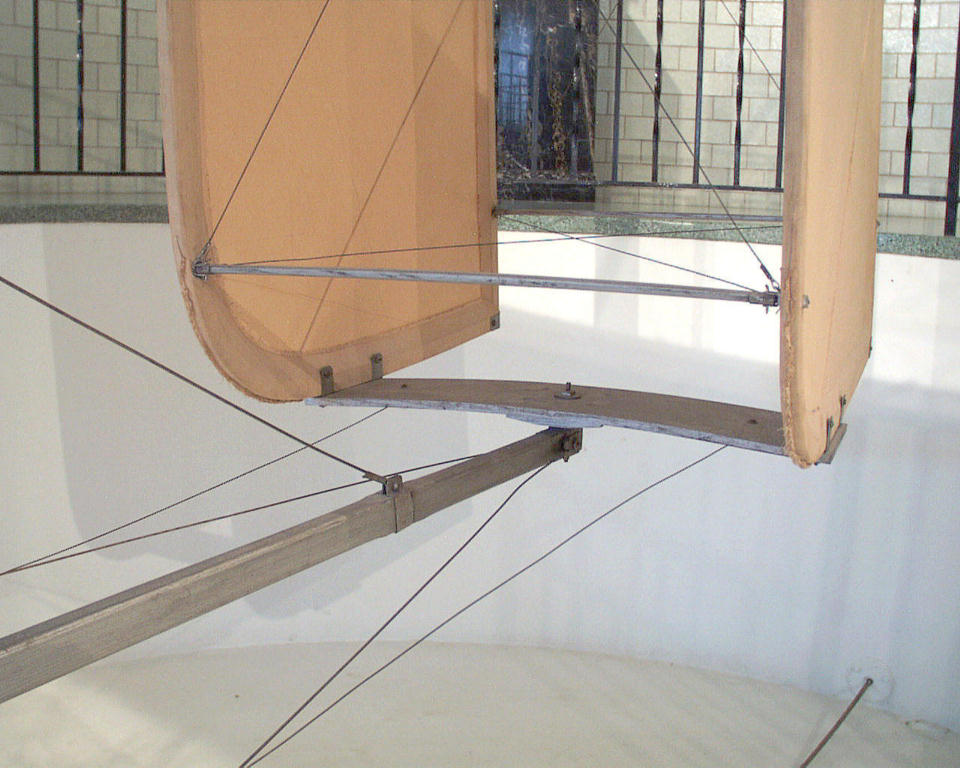
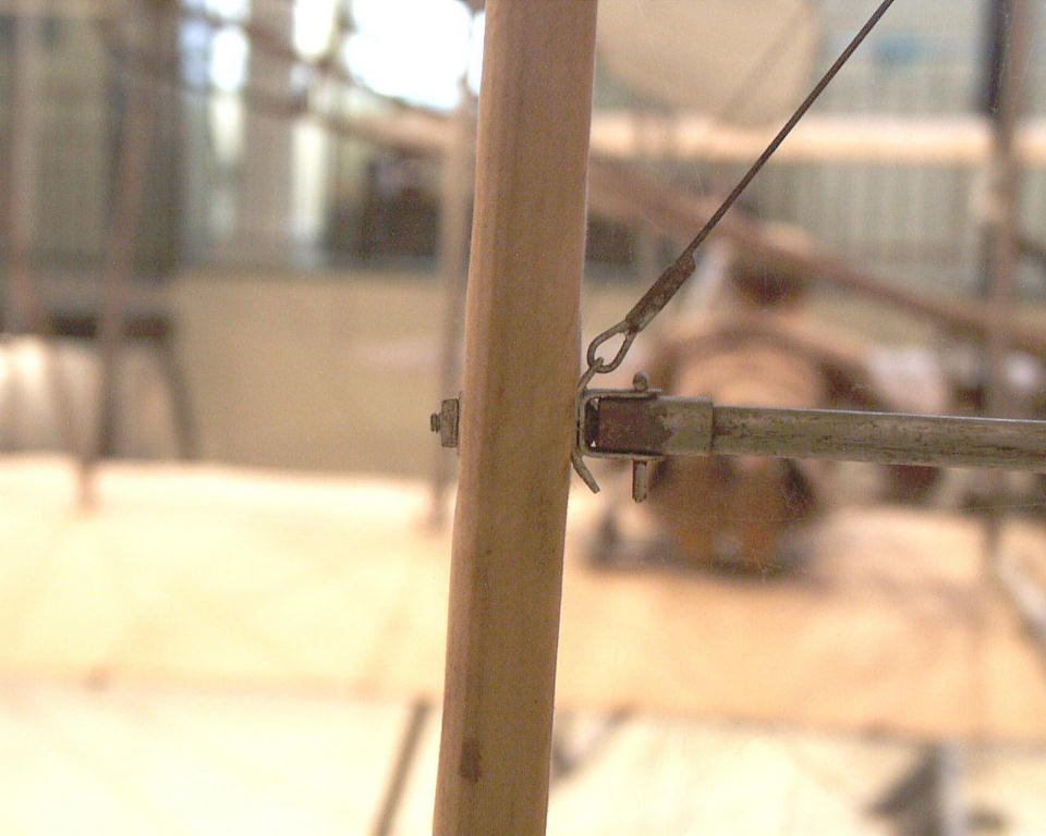
Two long outriggers attached to the rear spars support the rudder.
These outriggers are hinged so that if the rudder strikes the
ground, they pivot upwards.
|

|
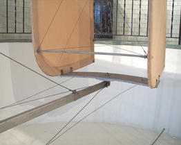
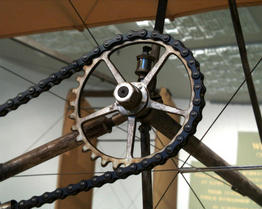
(Left) The rudder looks like a large box-kite with two control
surfaces spaced about 18 inches apart. (Above) It rests on the
trailing end of the bottom outrigger.
|
The rudder pivots on the outriggers. As the pilot moves the rudder
control lever in the cockpit right or left, the rudder moves
accordingly.
|
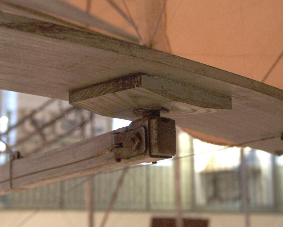
The rudder control surfaces are mounted to a pivot board, positioned
closer to the leading edge than the trailing edge. This arrangement
makes the rudder tend to straighten itself in the air stream.
|
The top of the rudder is similar to the bottom, with a pivot board
holding the rudder surfaces. However, the top pivot comes down from
the top rather than up through the bottom of the board.
|
The framework of the rudder is not glued. Instead, the tension of
the cloth the covers it keeps the wooden pieces together. This metal
tab at the trailing edge keeps the two adjoining pieces in
alignment.
|

The rudder is rigged with diagonal bracing wires like the wings and
the elevator. The Wrights used this same truss system throughout the
airframe because it was both light and strong.
|
A look up the centerline of the Flyer, through the rudder to the
wings and elevator.
|
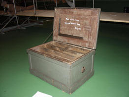
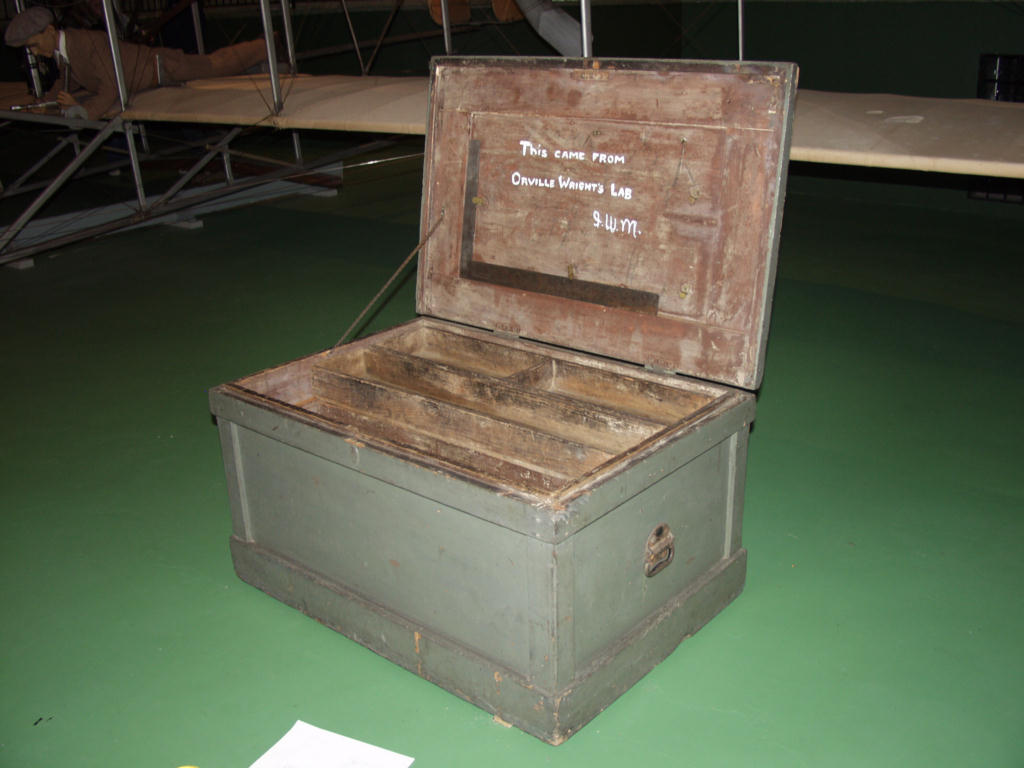
Here's something you're not likely to see in a visit to Wright Hall
-- the inside of the Wright tool chest. The writing on the inside of
the lid says, "This came for Orville Wright's lab. I.W.M. The
initials stand for Ivonette Wright Miller, Orville's niece.
|
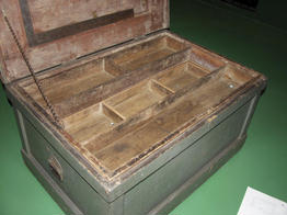
The chest has five sliding drawers inside, arranged so a workman has
access to the entire contents of the chest without having to remove
a drawer. Here the two top drawers are spread apart, revealing one
of the drawers on the middle level.
|
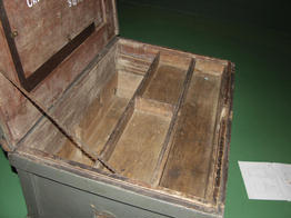
With the two top and the two middle drawers pushed toward the front
of the chest, you can see single deep drawer at the bottom.
|
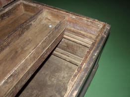
And here are the two top, two middle, and single bottom drawer all
slid towards the back of the tool chest, revealing a deep "well"
where large tools can be stored.
|
|
Other Voices
|
|
|


