|

 Up
Up
 The 1901 Wright
Wind Tunnel

(You are here.)
The
1903
Wright
Flyer I

The
1905
Wright
Flyer III

  Need
to Need
to
find your
bearings?
Try
these
navigation aids:
If
this is your first
visit, please stop by:
Something
to share?
Please:
|
|
Available in Française, Español, Português, Deutsch, Россию,
中文,
日本, and others.
 fter
the 1901 flying season at Kitty Hawk, the Wrights were seriously
discouraged. Neither of their gliders from 1900 or 1901 had worked
as anticipated or had produced sufficient lift. They had begun to
suspect that the data they were working with to design their
aircraft was incorrect. This data was gleaned from the experiments
of
Otto Lilienthal who, before his death in 1896, had designed 16
gliders and made thousands of glider flights, many more than any
pilot/scientist before or since. His unquestioned success gave
credence to his data. fter
the 1901 flying season at Kitty Hawk, the Wrights were seriously
discouraged. Neither of their gliders from 1900 or 1901 had worked
as anticipated or had produced sufficient lift. They had begun to
suspect that the data they were working with to design their
aircraft was incorrect. This data was gleaned from the experiments
of
Otto Lilienthal who, before his death in 1896, had designed 16
gliders and made thousands of glider flights, many more than any
pilot/scientist before or since. His unquestioned success gave
credence to his data.
Whatever the accuracy of Lilienthal's data,
the Wrights had come to a dead end. They simply did not know what to
do to improve the performance of their gliders. If they built a
third glider at this point, its design would be nothing more than
guesswork. And at their present pace, building and testing one
glider per year, it could be several lifetimes before they
discovered a workable design. Even then, they wouldn't know if it
was the best possible design.
They decided to discard Lilienthal's data and generate their own.
They built a wind tunnel, the second in America. (The first was
built by
Alfred Zahm.) Over the winter of 1901-1902, they tested over 200
wing shapes to find the most promising, then thoroughly investigated
about 45 shapes to determine the very best. To do this, they built
two instruments for their wind tunnel, one to measure lift and
another to measure the ratio of lift to drag.
When they compiled all their data, they were surprised to find
that Lilienthal had been correct. They, in fact, had been at naive
in the way they applied his data. Lilienthal investigated a single
wing shape that he used for all his gliders and his data was correct
for that shape only. The Wrights had presumed that even
though they used different shapes, Lilienthal's data for lift and
drag would be close enough. They were astonished to find just how
much difference in performance there was between wing shapes. Armed
with this new knowledge, they felt ready to get back in the air.
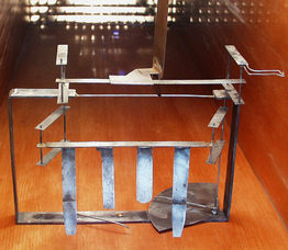
We built our tunnel and the balance instruments from the same
materials that the Wrights used, down to to the used hack saw blades
and spoke wire. But despite their crude construction, we found them
to be amazingly sensitive.
|
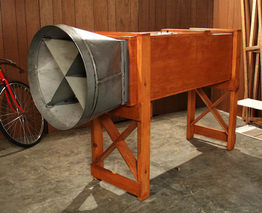
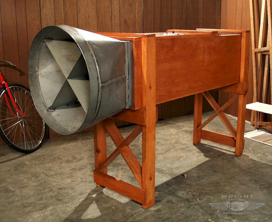
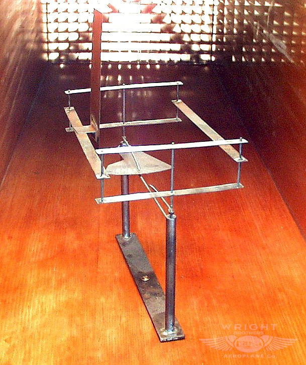
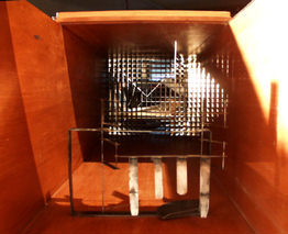
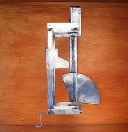
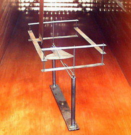
The Wrights' wind tunnel is little more than a wooden box with a tin
scoop on one side to direct and compress the air stream.
|
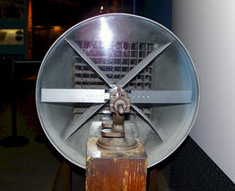
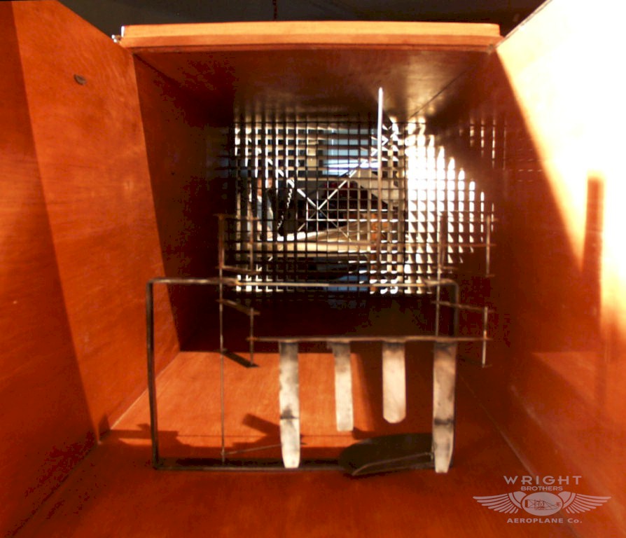
The air enters the tunnel through a two-stage "straightener"
designed to remove the roiling vortices that spin off the fan blade.
|
The air then travels down the length of the tunnel, allowing it to
settle into a uniform stream before it reaches the instrument.
|
There is a glass window directly over the instrument. Wilbur and
Orville stood on a box and looked down through this windows to read
the scales that measured lift and drag.
|
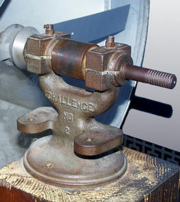
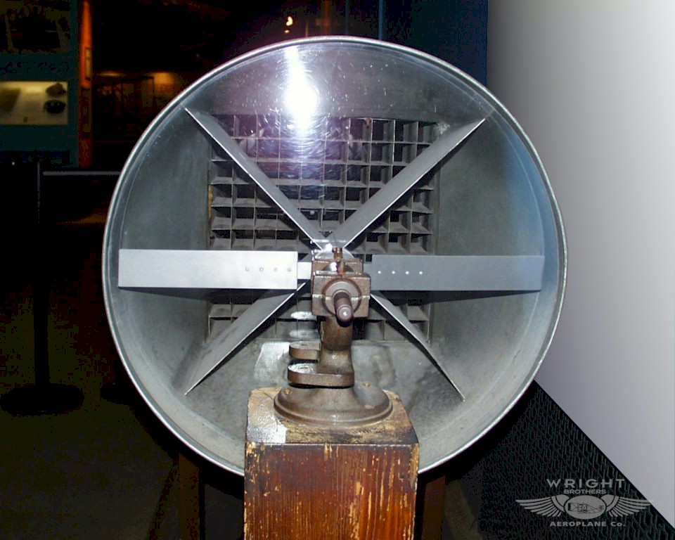
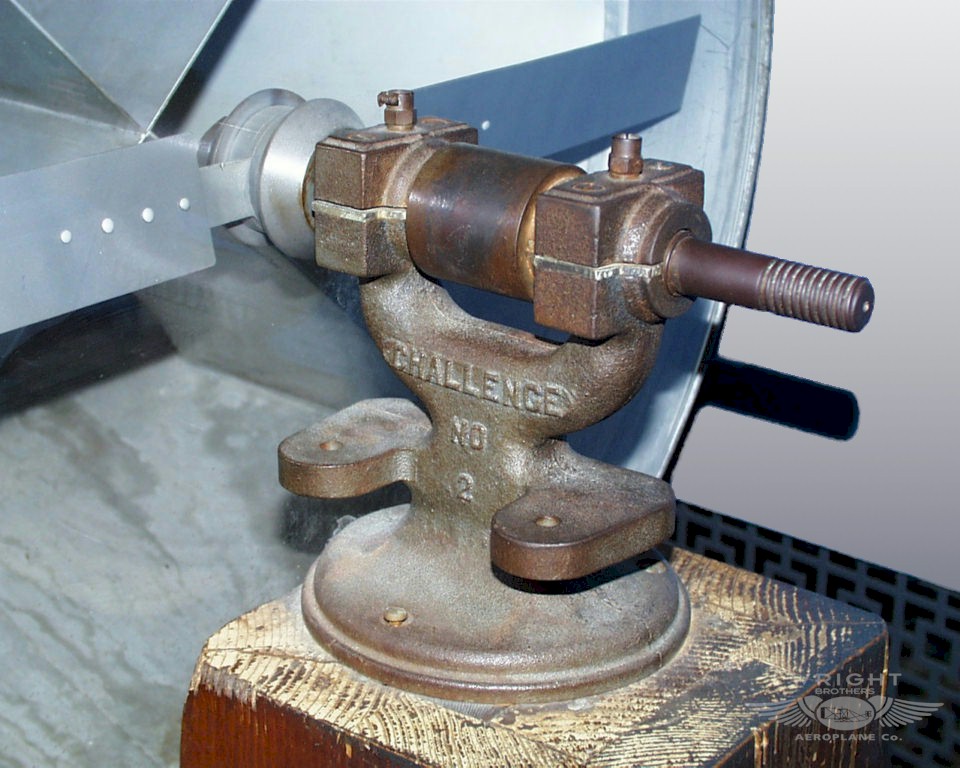
The fan blade was mounted on a grinding arbor, a tool that was
normally used to spin abrasive grinding wheels.
|

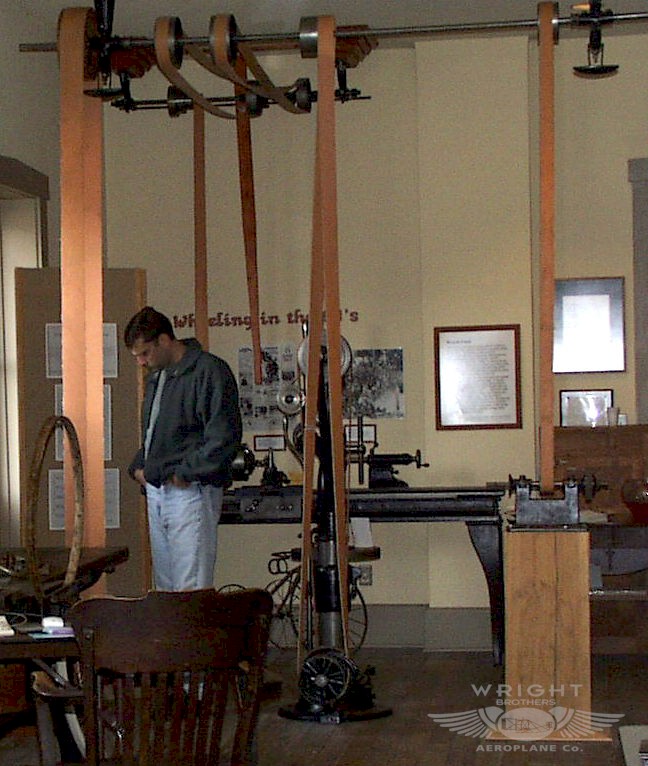
The arbor was spun by a leather belt that was turned by a series of
line shafts and pulleys.
|
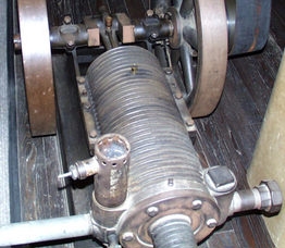
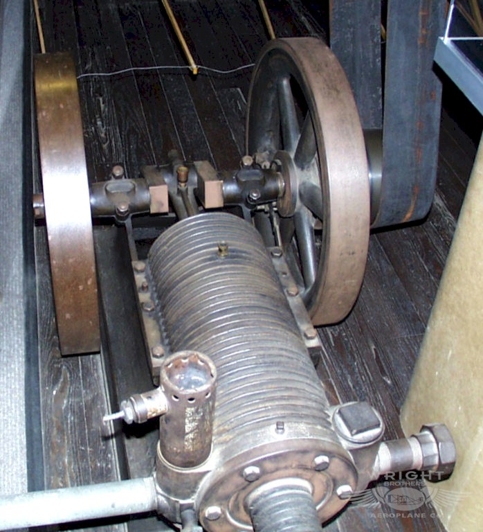
The line shafts were turned by a one-cylinder engine that ran on
natural gas. This one engine, in fact, powered all the tools in the
Wrights' bicycle shop.
|
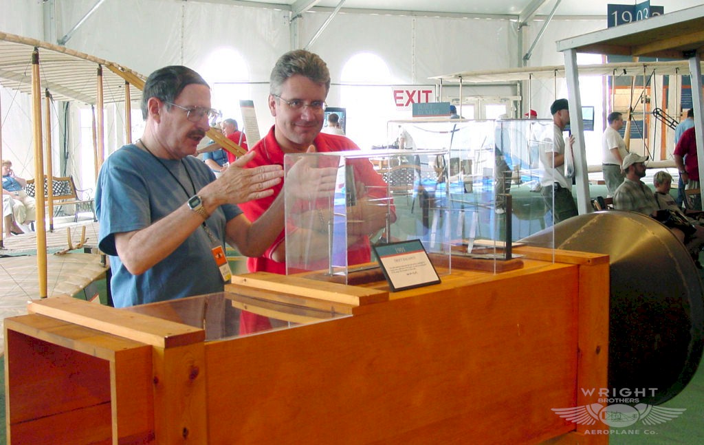
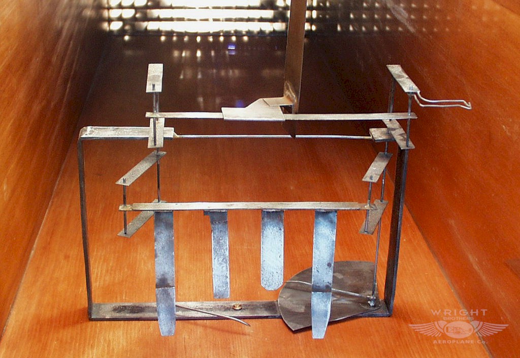
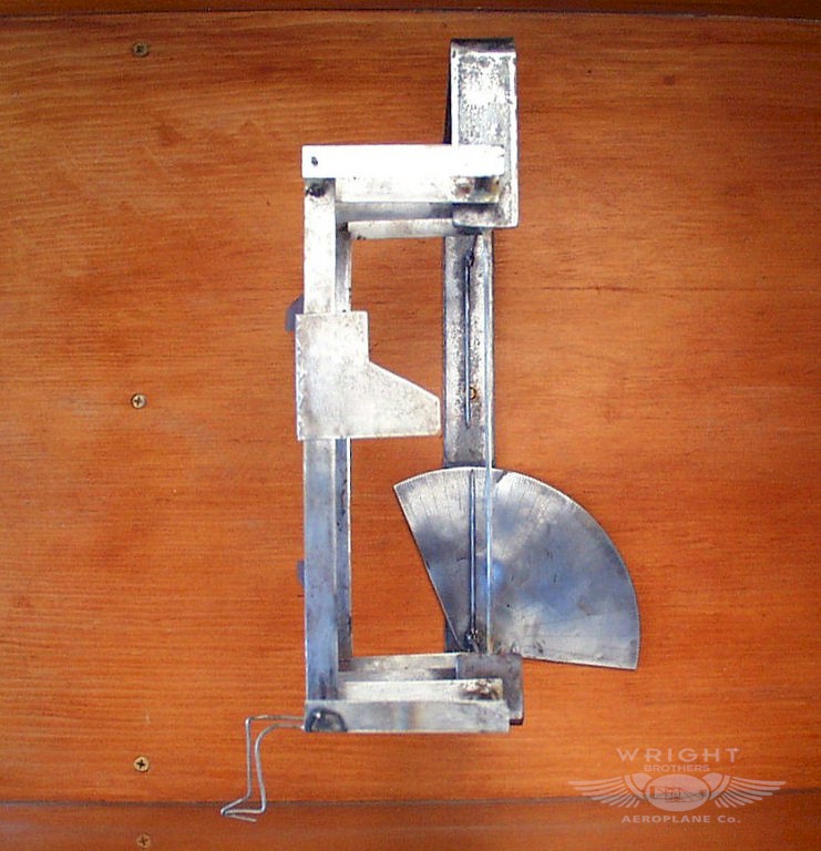
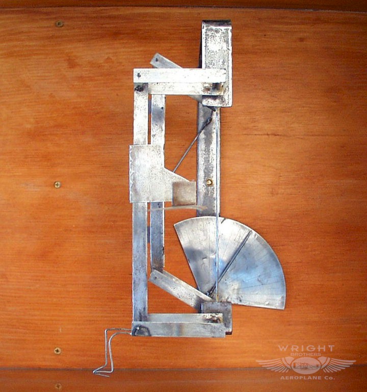
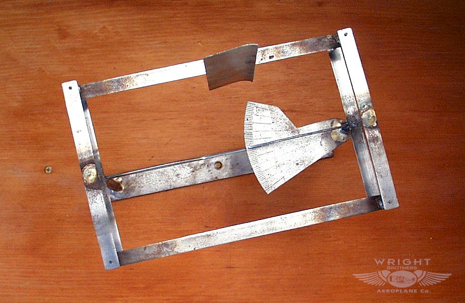
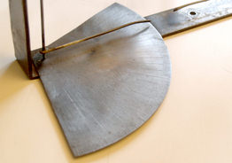
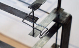
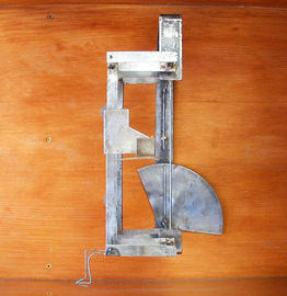
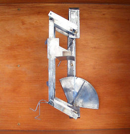
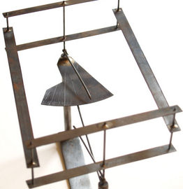
The first instrument the Wrights used they called the "lift
balance." It balances the lift generated by a wing shape against a
constant pressure on four metal plates or "fingers."
|
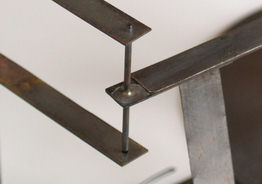
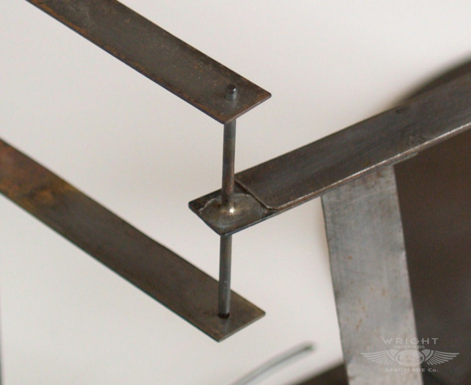
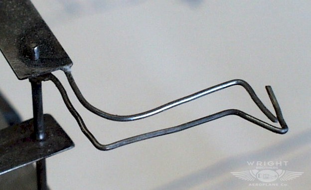
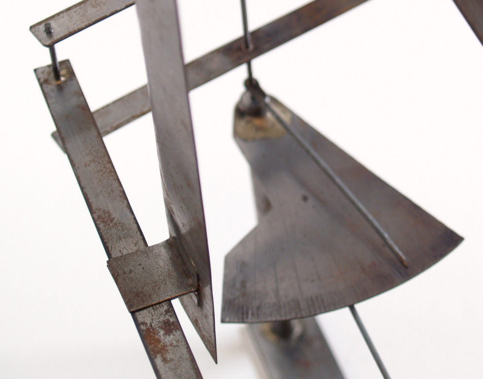
The moving parts of the balance pivot with almost no resistance.
The vertical parts – spoke wires – are ground to a point. The points
rest in small indentations in the horizontal parts – used hacksaw
blades.
|
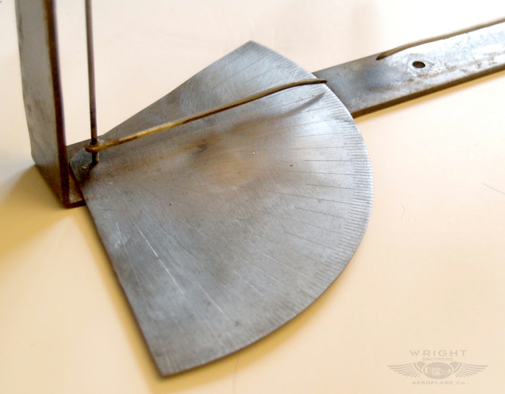
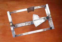
Each balance has a scale or "quadrant" marked off in degrees. By
reading the scale and applying a little
trigonometry, the Wrights could predict how much lift or drag a
wing shape would produce.
|
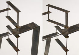
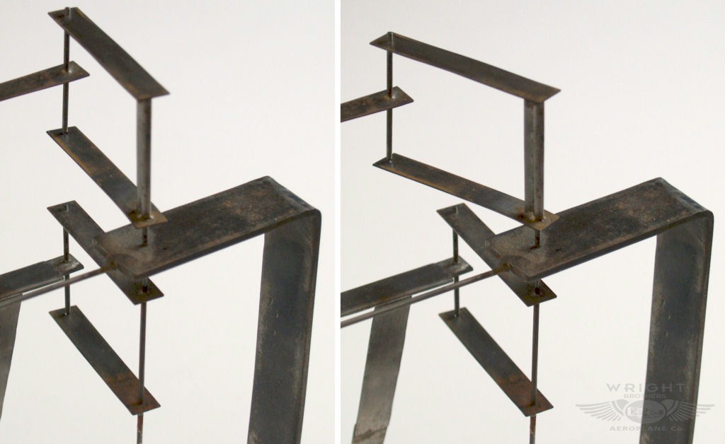
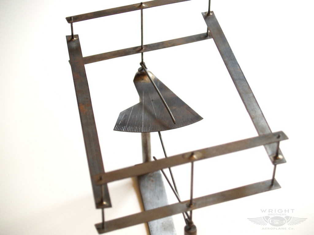
On the lift balance the top set of "arms" are friction-fit to their
vertical shafts. This allow you to adjust the position of the top
arms in relation to those just below.
|
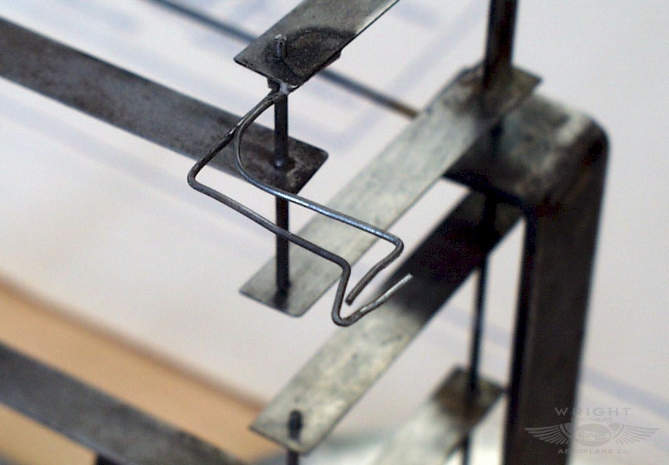
The lift balance also has an indicator to help calibrate and adjust
the instrument.
|
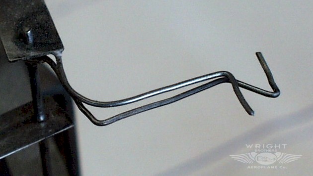
When the pointer is in the center of the "V," the balance is
properly adjusted.
|
When it's off-center, adjustment is needed.
|
To use the lift balance place it in the wind tunnel so the long
horizontal arms are perpendicular to the air stream. With the air
blowing, make sure the indicator is centered and the scale pointer
in on "0."
|
Mount the wing shape on the tab that protrudes from the long upper
arm. Adjust the shape so it's the proper "angle" of attack" to the
air stream.
|
Turn on the wind for a few moments and let the pointer come to a
rest over the scale. Turn off the wind. Note that the indicator is
no longer aligned with the "V."
|
Holding the pointer steady on the scale, move the top arms so the
indicator is centered. Turn on the wind and check that it remains
so. You may have to make several small adjustments to the top arms
until it does. When it stays centered, read the scale. The
sine of
the angle indicated is the coefficient of lift for that particular
wing shape.
|
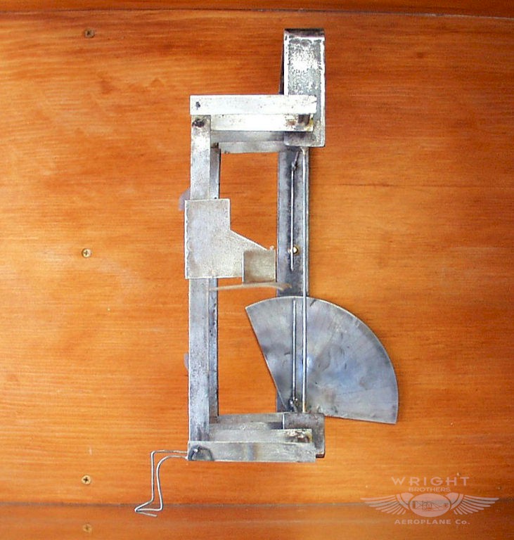
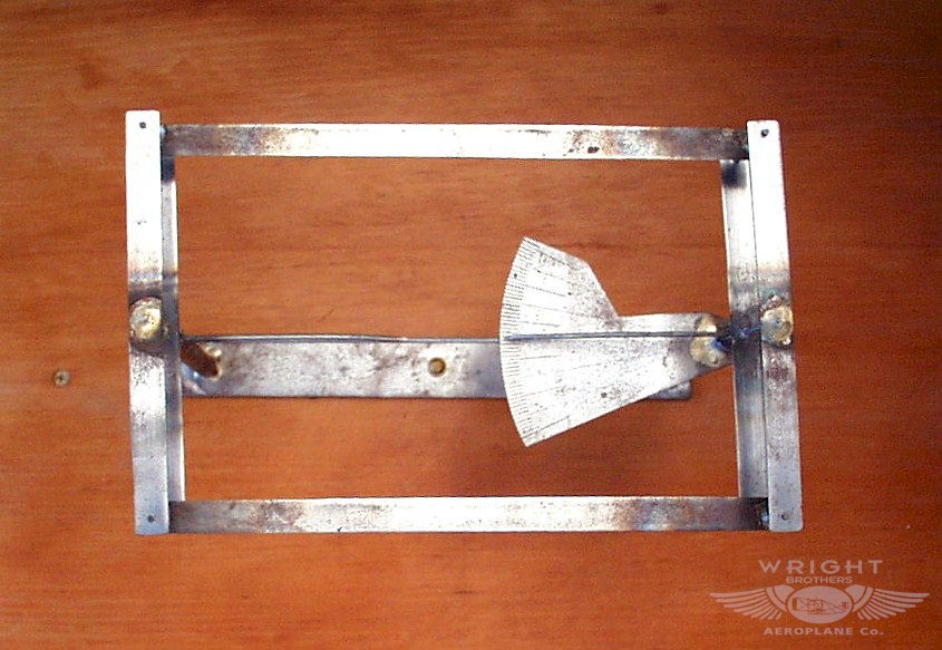
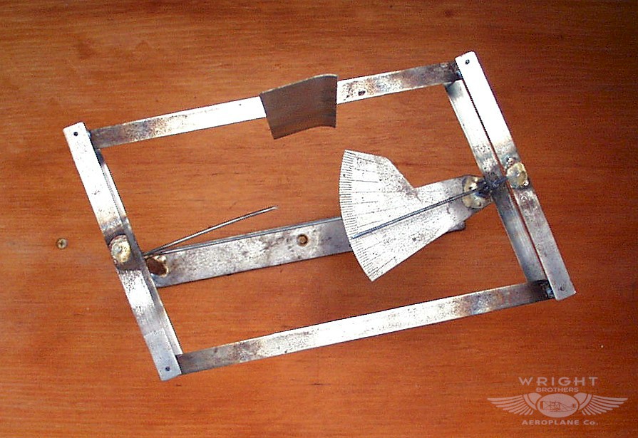
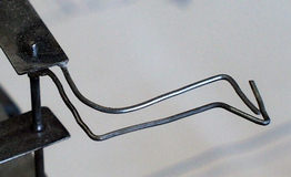
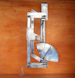
The second instrument the Wrights called the "drift balance."
Drift was their word for
what we now call drag. The
scale doesn't measure drag, however. It measures the ratio of lift
to drag. This is an extremely important number in aircraft design.
The higher the ratio – the more lift and the less drag – the more
efficient the wing shape.
|
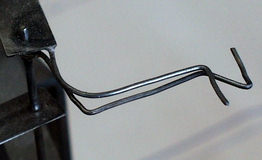
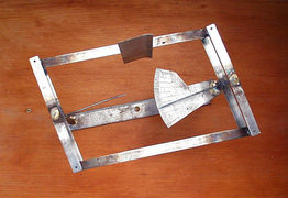
Notice that each of these balances has two pointers, one of which points to nothing.
The Wrights added the second pointer so the pressure of the wind on
the sides of the pointers would cancel each other out and not
interfere with the measurement.
|

To use the drift balance, place it in the wind tunnel with the long
arms parallel to the air stream. Turn on the wind and make sure the
pointer remains on "0."
|
Mount a wing shape on one of the long arms so the chord is parallel
to the arm. Turn the balance so the wing is at the desired angle of
attack to the air stream.
|
Turn on the wind, let the pointer come to rest, and read the angle
on the scale. Add this angle to the angle of attack. The
tangent of
the resulting angle is the ratio of lift to drag.
|
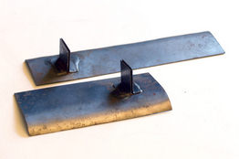
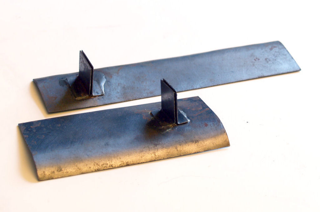
To mount the airfoils on the balances, the Wrights soldered two
small brackets to the top surface of each foil, so close together
that the brackets were almost touching.
|
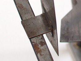
These brackets slip over the crossbars of the balances. The fit is
snug, but not so tight that the foils cannot be easily mounted and
dismounted.
|
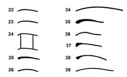
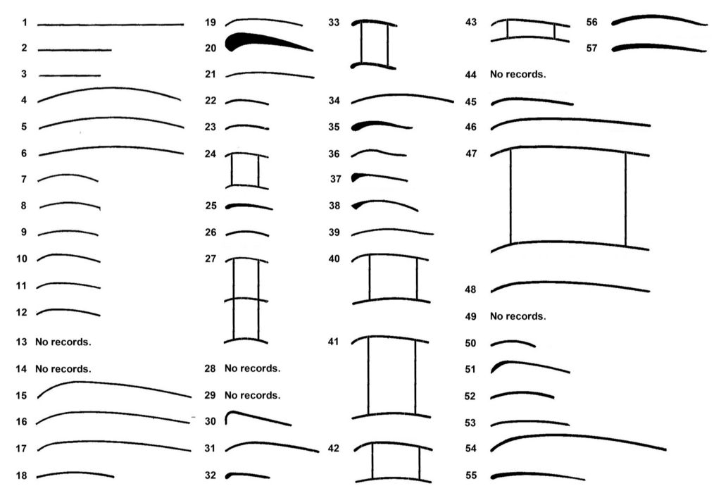
The Wrights made preliminary tests on over 200 wing shapes, then
thoroughly investigated 57 of the most promising. The foils are made
of sheet steel; thicker portions are built up with wax.
|
|
|