|

 Up
Up
 1904-05 Engines
(You are here.)

  Need
to Need
to
find your
bearings?
Try
these
navigation aids:
If
this is your first
visit, please stop by:
Something
to share?
Please:
|
|
Available in Française, Español, Português, Deutsch, Россию,
中文,
日本, and others.
 he
1903 Flyer engine was damaged beyond repair when the wind overturned
the Flyer after the fourth flight on 17 December 1903. At
the beginning of 1904, the Wrights built two similar motors to continue
their test flights, referred to as Wright Engines No. 2 and No. 3.
Each had four horizontal cylinders, but No. 2 was slightly larger
than No. 3, displacing 214 cubic inches (3.5 liters) to No. 3's 201
cubic inches (3.29 liters). No. 2 was also slightly heavier,
weighing 240 pounds (108.8 kilograms) with water and oil. In both
engines the volume of water surrounding the cylinders was increased
for better cooling. Other improvements included a geared fuel pump,
a better oil pump, and a better distribution of lubrication. There
was also a
compression release mechanism to aid starting and to allow the pilot
to quickly cut power. This unique mechanism became a standard
feature on Wright engines for years. he
1903 Flyer engine was damaged beyond repair when the wind overturned
the Flyer after the fourth flight on 17 December 1903. At
the beginning of 1904, the Wrights built two similar motors to continue
their test flights, referred to as Wright Engines No. 2 and No. 3.
Each had four horizontal cylinders, but No. 2 was slightly larger
than No. 3, displacing 214 cubic inches (3.5 liters) to No. 3's 201
cubic inches (3.29 liters). No. 2 was also slightly heavier,
weighing 240 pounds (108.8 kilograms) with water and oil. In both
engines the volume of water surrounding the cylinders was increased
for better cooling. Other improvements included a geared fuel pump,
a better oil pump, and a better distribution of lubrication. There
was also a
compression release mechanism to aid starting and to allow the pilot
to quickly cut power. This unique mechanism became a standard
feature on Wright engines for years. These engines evolved more
than they were planned. According
to Charles Taylor, "We didn't make any drawings. One of us would sketch out the part
we were talking about on a piece of scrap paper...." Orville Wright's diary of 1904
has the entry, "Took old [1903] engine apart to get measurements for making new
engine."
Engine No. 2 was used to power the 1904 Wright Flyer II and the1905 Wright Flyer
III. When first built, it produced 16 horsepower,
and this improved as the engine "broke in" and the cylinders
smoothed. The Wrights continued to improve it over the next two
years and by the time the engine was retired in 1905, the horsepower
had increased to 21.
Engine No. 3 was never
used on an airplane. Instead, it was used in the shop
as a test-bed for engine experiments and a power source for propeller experiments.
When the Wrights found something that improved the performance of
Engine No. 3, it was often transferred to Engine No. 2. This third motor eventually achieved 25 hp, twice that of the
original Wright motor of
the same size. It was last run in 1937 at the Henry Ford Museum
for the dedication of the restored Wright Cycle Shop and Wright home in
Greenfield Village.
Engine No. 2 was cannibalized in 1916 to restore the engine in
the 1903 Wright Flyer. In 1946 or 1947, Orville borrowed the crankshaft
from Engine No. 3 to restore Engine No. 2 for the 1905 Flyer III as
it was being rebuilt. This crankshaft was made new and
replaced in Engine No. 3 in 2002. The rebuilt engine No. 2 is displayed on the restored 1905 Flyer
III at
Carillon Park
in Dayton, OH. The restored Engine No. 3 can be seen at the
Dayton Engineer's Club.
Specifications for Engine No. 2:
- Cylinders: 4
- Stroke: 4 in (10.2 cm)
- Bore: 4-1/8 in (10.5 cm)
- Displacement: 214 in3 (3.5 l3)
- Horsepower:16 to 21
- Ignition: Make-and-brake powered by low-tension (10-volt)
magneto.
- Weight: 220 lbs (81.6 kg) dry
- Compression release, fuel injection
Specifications for Engine No. 3:
- Cylinders: 4
- Stroke: 4 in (10.2 cm)
- Bore: 4 in (10.2 cm)
- Displacement: 201 in3 (3.3 l3)
- Horsepower:18 to 25
- Ignition: Make-and-brake powered by low-tension (10-volt)
magneto.
- Weight: 180 lbs (81.6 kg) dry
- Unique features: Compression release, fuel injection,
auxiliary exhaust ports in cylinders.
References:
- Hobbs, Leonard S. The Wright Brothers' Engines and Their design. Washington, D.C.:
Smithsonian Institution Press, 1971, pp 29-33.
- McFarland, Marvin W. (ed) The papers of Wilbur and Orville Wright. McGraw-Hill
Book Co., New York, 1953, p 1214-1215.
- Lippincott, Harvey H. Propulsion System of the Wright Brothers. In Wolko, Howard S.
(editor), The Wright Flyer, an Engineering Perspective. The Smithsonian Institution Press,
1987, pp 86-87.
[Submitted by Joe W. McDaniel]
|

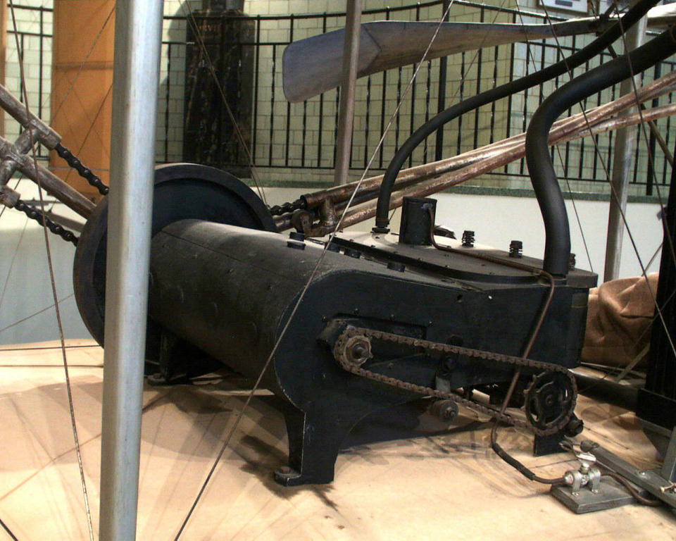
Engine No. 2 was used to power the Wright Flyer II in 1904 and the
Wright Flyer III in 1905. The restored engine is on display in the
Wright Flyer III in Carillon Park, Dayton, Ohio.
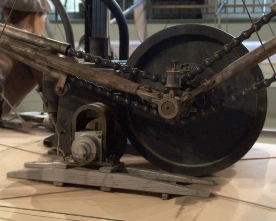
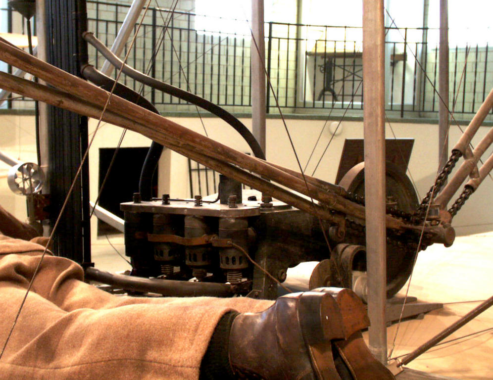
Like the original Wright engine, ignition Engine's Nos. 2 and 3 were
powered by a low-tension magneto. The magneto was turned by a
friction wheel the rubbed against the engine's flywheel.

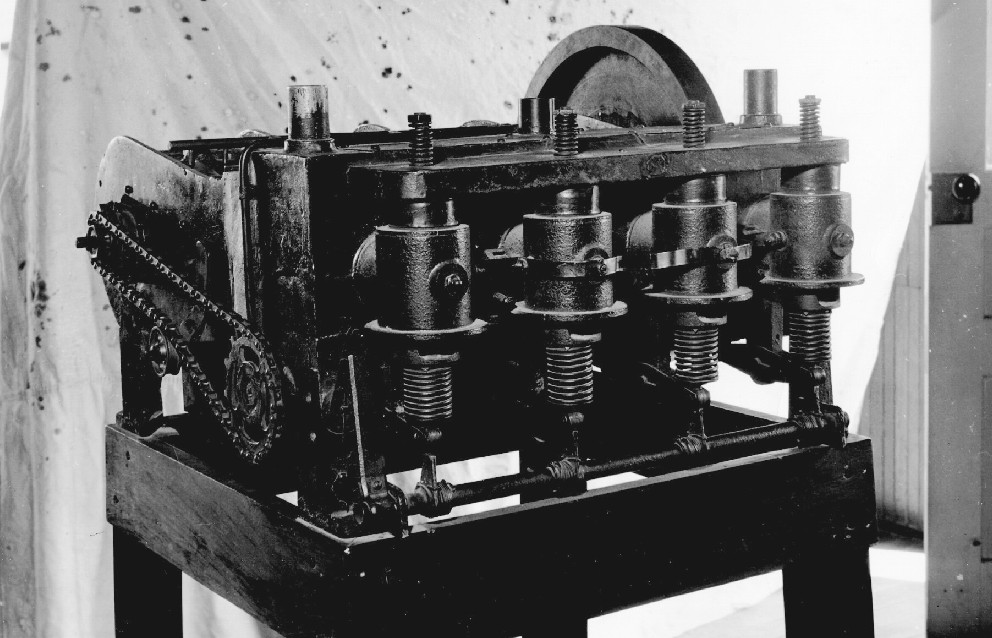
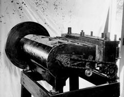
Engine No. 3 on display in 1937 at Greenfield Village (part of
the Henry Ford Museum in Dearfield, MI). It was run at this time but
shut down after it developed a crack in one of the cylinders.
The underside of Engine No. 3. The oval shapes just below the cam
shaft are the oil pump and the fuel pump The fuel pump metered
the gasoline as it dripped into the intake port, providing a
rudimentary form of fuel injection.
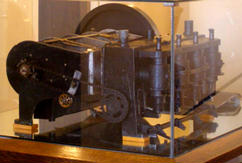
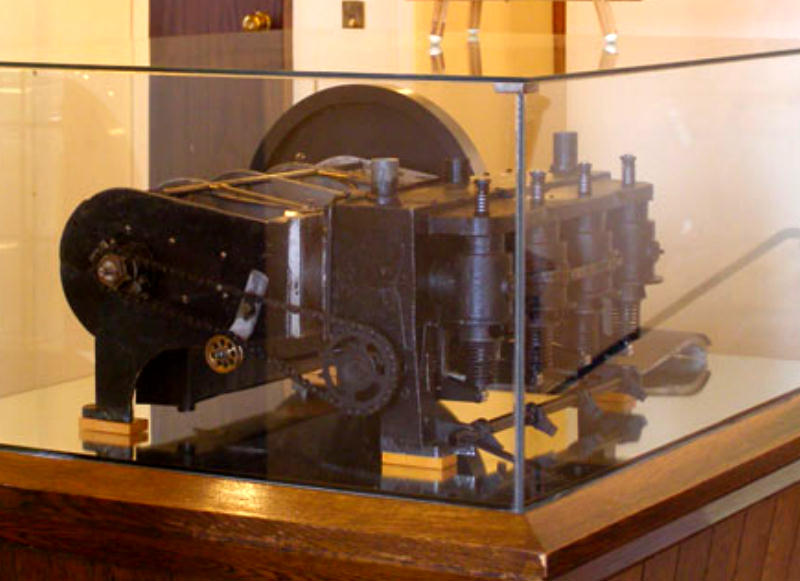
Wright Engine No. 3 on display in the upstairs lobby of the Dayton
Engineers Club.
|
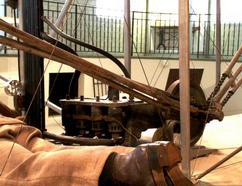
Engine No. 2 in the Wright Flyer III, as seen from the rear.
Engine No. 3 was never used on an airplane, but
served as a test bed, providing the Wrights
with valuable experience in engine design.
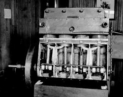
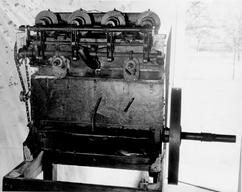
Engine No. 3 with the crank case cover removed. Note the water
jacket in completely separate from the crankcase, unlike Engines
Nos. 1 and 2. There are auxiliary exhaust ports (small holes) in the cylinder
walls between the jacket and the case to allow hot gases to escape.
This was one of the many experiments the Wrights conducted with this
engine -- they wanted to see if the additional exhaust ports would
help keep the engine running cooler. It apparently worked; they
incorporated this feature on later engines.

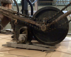
Engine No. 3 was also used for experiments whenever the Wrights
needed a source of power. In this 1907 investigation, the Wrights
taxied along the Great Miami River on pontoons to see if their
propellers and test engine would provide enough thrust to reach
take-off speed from the water.
|